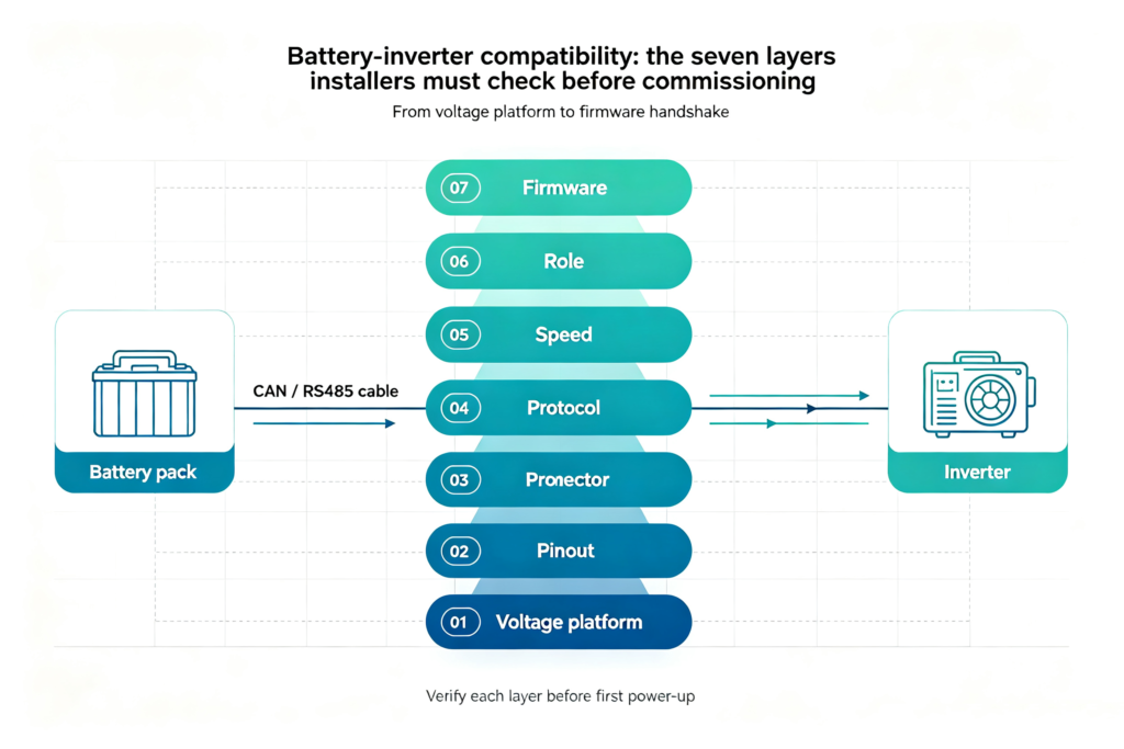
An inverter and battery pair is a seven-layer check, not a cable swap. Both voltage and the communication protocol have to line up, and a single missed layer is enough to stop the system from commissioning. If any one of those layers is wrong, the inverter either refuses to talk to the battery, misreads state of charge, or — in the worst case — charges the pack past its safe limit. The seven layers, in order, are: voltage platform, connector, pinout, communication protocol, communication speed, device role, and firmware. Work them top to bottom and you catch the overwhelming majority of field failures before the system is powered up.
This guide is written for the installer or technical buyer who is about to wire a new lithium battery bank to an inverter, and wants to know exactly which boxes to tick before turning anything on. It also applies if you are evaluating a battery supplier — the answers to the seven compatibility questions tell you whether the supplier is genuinely qualified or just reselling a pack.
1. Why compatibility is the most common cause of field failure
Across residential and small-commercial storage, the majority of “my battery and inverter don’t talk” tickets share the same root cause: someone assumed that because the connector looked right, the rest would follow. In a survey of BMS-assisted support cases, voltage mismatch and protocol mismatch together account for more than half of all installation-day failures, with wiring and DIP-switch errors making up most of the remainder. Equipment damage is rare but not zero — the documented failure mode is a battery that is asked to charge at a current the BMS never authorised, which trips a pack-level protection event and may lock the pack out until a service tool is used.
For B2B buyers, the practical question is therefore: what does the supplier have to demonstrate, in writing, before you sign the purchase order? The rest of this article is the checklist that answer breaks down into.
2. The seven compatibility layers
Every successful battery-inverter pairing has to clear the same seven checkpoints. Treat them as a hierarchy: if layer 1 fails, you do not need to look at layer 4. If layer 1 passes and layer 4 fails, the system will appear to wire up correctly and then fail at commissioning.
| # | Compatibility layer | What must match | Typical symptom if wrong |
|---|---|---|---|
| 1 | Voltage platform | 12V / 24V / 48V / 51.2V LV or HV stack | Inverter refuses to start, or BMS trips immediately |
| 2 | Connector | RJ45, terminal block, DB9, or proprietary | Plug does not seat, or pins do not line up |
| 3 | Pinout | CAN-H/L, RS485-A/B, GND, wake-up | No data, intermittent data, or equipment damage |
| 4 | Communication protocol | Pylon, Victron, Growatt, GoodWe, Modbus RTU, etc. | Battery detected but SOC is missing or wrong |
| 5 | Communication speed | CAN bit rate / RS485 baud rate / parity | Timeouts, error codes, offline after a few seconds |
| 6 | Device role and address | Master/slave, DIP switch, bus termination | One pack in parallel not seen; intermittent dropouts |
| 7 | Firmware | Approved BMS and inverter revision | Worked yesterday, broken after a firmware update |
For leekooenergy battery packs, the engineering team maintains a layer-by-layer compatibility matrix for the inverter brands most commonly used in our customer projects. The matrix is available on request with a project brief, because exact model and firmware numbers change faster than any printed document.
3. Voltage platforms: match the platform before you match the protocol
Voltage is the layer that people skip first, because it is the layer that “should be obvious” — but it is also the layer where a wrong assumption is most expensive. A 48V nominal LiFePO4 pack is only electrically compatible with a 48V or 51.2V inverter. A high-voltage battery stack (typically 100V to 500V+, built by series-connecting modules) is only electrically compatible with an HV-class inverter such as the Huawei SUN2000 or SolarEdge Home Hub. No amount of CAN protocol work can make a 48V pack talk safely to an HV inverter, or vice versa.
| Voltage class | Nominal range | Typical inverter examples | Typical use |
|---|---|---|---|
| 12V / 24V | 11–29V | Small off-grid, RV, marine | Light loads, single-pack systems |
| 48V / 51.2V LV | 44–58.4V | Growatt MIN/MID, Sungrow SH-RS, Goodwe ET/EH, Victron MultiPlus-II, Deye SUN-G3 | Residential storage up to ~20 kWh, dominant class globally |
| High-voltage stack | 100–500V+ | Huawei SUN2000, SolarEdge Home Hub, Fronius GEN24 Plus, Sungrow SH-RS HV | Residential and light-commercial HV, premium segment |
For a standard 48V LiFePO4 rack or wall-mount pack, a 48V LV inverter is the path of least resistance. Stackable 48V packs let you scale capacity without changing inverter, which is the practical reason LV dominates the residential retrofit market in Europe, Australia and North America. If you are planning an HV stack, do that decision up front — it changes the battery, the inverter, the wiring, and the certification path.
4. CAN vs RS485: pick the protocol the inverter already supports
Once voltage is matched, the communication decision is no longer “which is better” but “which does this specific inverter already speak”. Both CAN and RS485 are differential serial buses that can carry the SOC, voltage, current limits, temperature and alarm data a modern hybrid inverter expects. The decision is dictated by the inverter manufacturer’s approved battery list, not by the interface speed on a datasheet.
| Attribute | CAN bus | RS485 / Modbus |
|---|---|---|
| What it defines | Bus communication and message arbitration | Electrical signalling; higher-level protocol still required |
| Common ESS use | Real-time BMS data and inverter closed-loop control | Monitoring, control, or daisy-chain battery communication |
| Topology detail | Termination, node IDs, approved cable | Termination, polarity, addresses, baud rate |
| Compatibility proof | Matching CAN protocol/firmware profile | Matching higher-level protocol, settings, pinout |
| RJ45 = match? | No. Same connector can hide different pinouts. | |
Two practical rules from the field. First, RJ45 is not Ethernet in this context — many BMS ports use an RJ45 jack but carry CAN-H, CAN-L and ground on pins that do not match T568B. Second, when an inverter manufacturer publishes a “CAN compatible” statement without naming the protocol profile (Pylon, BYD, Victron, GoodWe, Growatt and so on), that statement is not yet a compatibility confirmation. The protocol name is the test.
5. Step-by-step: wiring a battery to an inverter
The following sequence is the one our engineering team uses during bench commissioning. It is deliberately conservative — every step is one that, if skipped, has caused a support case we still remember.
- Confirm the exact battery and inverter models. Write down the full model number and firmware version of each. One inverter family can carry several regional or hardware variants with different protocol support.
- Verify electrical compatibility. Voltage class, continuous charge/discharge current, and the BMS’s stated protection limits should all sit inside the inverter’s published envelope.
- Identify the supported communication method. Read the inverter manual’s battery section, not the marketing datasheet. The supported list will name the protocol — not just the interface.
- Check the cable pinout. Battery-side port name, inverter-side BMS port, CAN-H, CAN-L, RS485-A, RS485-B, ground, and any wake-up or enable lines. Make or order a cable that matches both ends.
- Set addresses and roles. Configure master/slave and DIP switches before any pack is powered. In a parallel battery bank, duplicate IDs are the number-one reason one pack is “missing”.
- Select the BMS profile in the inverter. Most hybrid inverters keep a menu of supported battery brands and protocol versions. Pick the one that matches the BMS firmware.
- Power up in the documented order. BMS first, then inverter, then close the contactor. Some inverters need to see the BMS heartbeat before they will close their DC bus.
- Verify SOC, voltage and alarms on the inverter screen. Walk through charge limit, discharge limit, low-SOC cut-off, and a forced alarm to confirm the inverter reacts.
- Run a controlled charge and discharge test. Don’t leave site until you have seen the system absorb a programmed charge cycle and deliver a programmed discharge without a single communication error in the log.
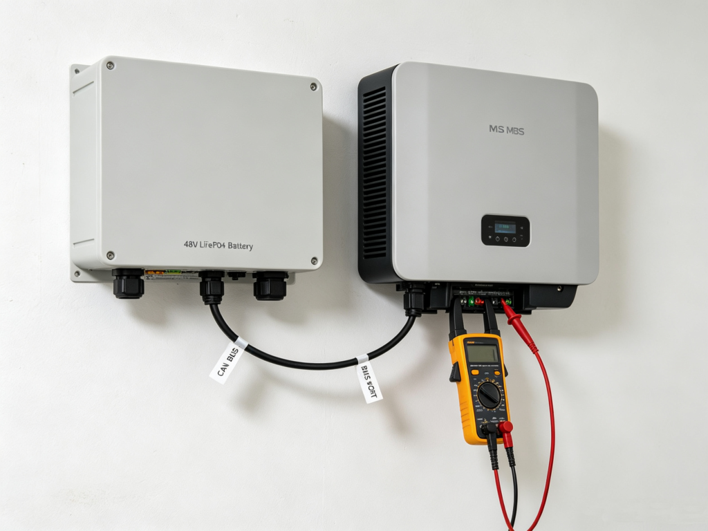
6. When the battery is detected but not controlled: a troubleshooting matrix
Even with a clean install, post-commissioning issues show up. The following matrix covers the eight symptoms we see most often in support tickets. For each, the first column is the most likely cause, the second is the cheapest first check.
| Symptom | Most likely cause | First check |
|---|---|---|
| No BMS icon, immediate comms error | Wrong port, cable, or pinout | Verify CAN/RS485 port labels on both ends against the manual |
| Battery detected but SOC missing | Wrong protocol profile selected | Confirm the named protocol, not “CAN compatible” |
| SOC or voltage is unrealistic | Scaling, byte order, or register mismatch | Compare raw frames with the protocol document |
| Works with one battery, not several | Duplicate IDs or wrong master selection | Check DIP switches and module sequence |
| Intermittent errors under load | Noise, grounding, termination, or routing | Inspect shielding and separation from power cables |
| Works short distance, fails after extension | Signal integrity or topology problem | Check data rate, termination, and cable spec |
| Inverter shows battery offline after a few seconds | Heartbeat or timeout mismatch | Confirm update interval and required periodic messages |
| Charge current stays very low | BMS reporting a dynamic limit | Check temperature, SOC, cell voltage and alarm state |
If the symptom does not clear after the first check, the next move is to capture live traffic with a CAN analyser or an isolated RS485-to-USB converter. With raw frames in hand, the question stops being “is something wrong” and becomes “which byte is wrong”, and the answer is usually a few minutes of register-map reading away.
7. Installer checklist before signing the commissioning report
- Battery model number, BMS firmware version, and the protocol profile name are recorded on the project sheet.
- Inverter model number, firmware version, and region variant are recorded on the same sheet.
- Voltage class confirmed against the inverter’s published envelope, including the low-SOC and end-of-charge cut-offs.
- Cable pinout verified at both ends with a continuity tester, including shield and ground.
- Bus termination, addresses, and master/slave roles set per the manufacturer documentation.
- BMS profile selected in the inverter menu and a screenshot saved to the project folder.
- One full programmed charge cycle and one full programmed discharge cycle completed with no communication errors in the log.
- Forced alarm test (cell over-voltage or over-temperature) confirmed visible at the inverter.
- Pinout, settings, firmware, and test results filed in the handover record.
For leekooenergy projects, the engineering team can pre-validate the configuration before production if you send across the inverter brand, full model, firmware, required battery capacity, system voltage, inverter power, and the project country. That step alone eliminates most of the field failures listed above.
8. Frequently asked questions
Q. Is CAN always better than RS485?
No. Either can work reliably when the product implementation, protocol and wiring match. Choose the interface approved by both manufacturers for that exact model pair.
Q. Can I use a normal Ethernet cable to connect the battery and inverter?
Only if both manufacturers specify the same pinout and cable type. RJ45 does not mean standard Ethernet wiring in this context. A wrong cable can prevent communication or damage equipment.
Q. Will the inverter and battery work together if the voltage matches but the protocol is different?
Not safely. Voltage compatibility and data compatibility are separate checks. A voltage match without a protocol match usually produces a battery that the inverter can neither read from nor write to.
Q. Can the inverter run the battery without BMS communication?
Some inverters allow a voltage-based fallback mode, but the protection behaviour and the charge limits are different. Use it only when both manufacturers explicitly approve that mode for the model pair.
Q. How do I know whether my inverter is on the approved battery list?
The inverter manufacturer’s compatibility document is the only authoritative source. Brand-level statements are useful for initial screening but do not guarantee model-level compatibility, especially after a firmware update.
Send your battery and inverter pair for a compatibility check
Provide inverter brand, model and firmware; the leekooenergy team returns a written compatibility note plus recommended firmware settings within one business day.