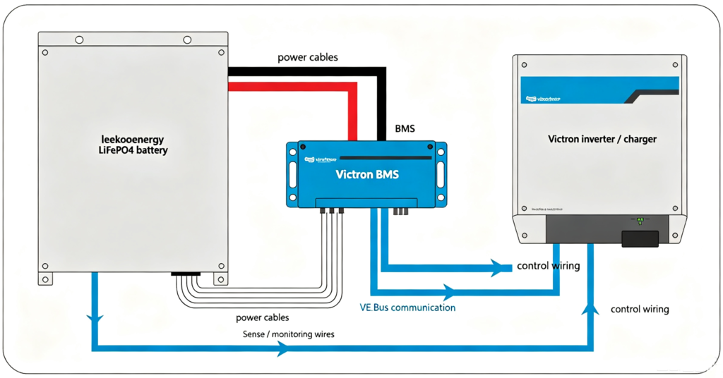
Integrating a Victron BMS with leekooenergy batteries means matching Victron’s VE.Bus control signaling and battery monitoring to the pack’s own BMS, so the inverter charges and loads the battery safely. The practical work is three wires: cell sensing to the pack BMS, VE.Bus control to the Victron inverter, and a battery monitor for state of charge. Do it in the order below and confirm each link before energizing.
This guide is written from the leekooenergy battery perspective — how a leekooenergy LiFePO4 pack presents to Victron control. It complements Victron’s own documentation; treat the official manuals as the source of truth for Victron hardware and this as the pack-side view.
Why Victron compatibility matters
Victron systems are common in off-grid and RV builds because of mature VE.Bus control and monitoring. A leekooenergy pack that speaks Victron’s language lets the inverter throttle charge on a cell fault and report state of charge in the Victron console — closed-loop control instead of blind running. The BMS 101 guide explains the monitoring and protection jobs the pack side must perform.
VE.Bus BMS V2
The VE.Bus BMS V2 is Victron’s control unit that manages charge and load disconnect based on cell signals from a compatible battery. It expects the pack to report cell-level faults; the leekooenergy BMS provides those via its communication output. Wire VE.Bus from the BMS to the inverter/charger, and keep the pack’s own protection active as the primary safety layer.
Lynx Smart BMS
The Lynx Smart BMS sits in the Lynx distribution system and adds current measurement and a Victron-side view of the bank. It is suited to larger 48V banks where you want Victron monitoring alongside leekooenergy cell management. Choose between VE.Bus BMS V2 and Lynx Smart BMS by system size and whether you already use the Lynx bus.
Step-by-step integration
- Confirm protocol. Verify the leekooenergy BMS output matches Victron’s expected signaling for your model.
- Wire cell sensing. Connect the pack BMS sensing lines per the leekooenergy manual — this is the primary protection.
- Run VE.Bus. Link the BMS control to the Victron inverter/charger; this is the charge/throttle path.
- Add the monitor. Install the battery monitor so state of charge shows in the Victron console.
- Configure limits. Set charge/discharge limits on both sides to the cell datasheet.
- Test safe. Run a controlled charge/discharge and confirm fault signaling trips correctly before load.
Model match table
| Victron model | Role | Fits | leekooenergy-side notes |
|---|---|---|---|
| VE.Bus BMS V2 | Controls charge/discharge | Small–mid 48V off-grid | Interface with pack BMS signal |
| Lynx Smart BMS | Control + monitoring | Large 48V bank | Needs Lynx busbar |
| Battery Monitor | SoC display | All ranges | Accurate after zero-calibration |
Common pitfalls
Installers often wire VE.Bus but leave the pack’s own protection unverified, or set charge limits on only one side. Both sides must agree on the cell datasheet limits; a mismatch trips the system under load or, worse, hides a fault. Confirm the leekooenergy BMS talks to the chosen Victron model in writing before order — the compatibility guide covers the generic matching logic.
Pre-integration checklist
Before any wire, confirm three things in writing: the leekooenergy pack BMS output matches the chosen Victron model’s expected signaling; the pack voltage sits inside the Victron device window; and the communication protocol (VE.Bus or the Lynx bus) is the one your inverter speaks. The Victron Smart BMS 12/200 battery management system is the entry point most integrators meet, and it expects clean cell-fault signaling from the pack. Skip the written confirm and you debug at commissioning instead of at quote.
Wiring the battery monitor step by step
Mount the monitor on the negative line between pack and load, with its sense wires to the pack terminals. Zero-calibrate it after a full charge so state of charge reads true. A monitor that was never calibrated is why consoles show wrong percentages; the fix is a calibration, not a new part.
Configuring charge limits on both sides
Set charge and discharge limits on the Victron side AND the leekooenergy BMS side to the cell datasheet – not to a default. A mismatch lets one side allow what the other cuts, tripping under load or hiding a fault. Align both to the same numbers before energizing.
Troubleshooting integration issues
- Console shows wrong SoC: recalibrate the monitor after full charge.
- System trips on load: BMS current rating below inverter peak – resize.
- No communication: protocol or register map mismatch – confirm with both suppliers.
- Charge will not start: VE.Bus control not linked or limit mismatch.
Documentation to keep
Save the protocol-match note, the configured limits, and the commissioning test result. A defensible record protects you if a field issue appears a year later, and speeds any warranty claim.
Model deep dive: VE.Bus BMS V2
The VE.Bus BMS V2 manages charge and load disconnect from cell signals coming off the pack BMS. It expects the leekooenergy pack to report faults cleanly; the pack’s own protection stays the primary safety layer. Wire VE.Bus from the BMS to the Victron inverter or charger, and keep both sides’ limits aligned to the cell datasheet. This is the control path, separate from the sensing path that protects the cells.
Model deep dive: Lynx Smart BMS
The Lynx Smart BMS lives in the Lynx distribution system and adds current measurement and a Victron-side view of the bank. It suits larger 48V banks where you already use the Lynx bus and want monitoring alongside leekooenergy cell management. Choose between the two by system size and whether Lynx is in the design – do not add Lynx just for one pack.
Integration safety checks
- Pack BMS sensing lines seated and torqued per manual.
- VE.Bus or Lynx control linked and recognized by the inverter.
- Battery monitor installed and zero-calibrated after full charge.
- Charge and discharge limits equal on both sides to the cell datasheet.
Commissioning test procedure
Run a controlled charge then discharge with the pack isolated from load, and confirm the Victron side shows correct state of charge and that a forced cell fault trips charge. Only after that passes connect the load. A safe commissioning test is what turns a wired system into a trusted one – skip it and you learn faults in production.
Firmware updates and version hygiene
Victron gear improves through firmware, and the BMS-to-inverter handshake depends on both sides running compatible versions. Before commissioning, note the firmware on the inverter, the BMS, the battery monitor, and the GX device, and confirm they are on a matched, current release. A mismatch is a common cause of “charging stops at 80%” or “BMS alarm on first connect” that looks like a hardware fault but is just version drift. Keep the version list with the commissioning document so a future service visit starts from a known state.
Update over a stable connection and re-verify the charge limits after each update – a firmware change can reset a parameter you tuned by hand. Treat firmware as part of the build, not an afterthought.
Remote monitoring with Victron VRM
With a GX device online, Victron Remote Management (VRM) shows state of charge, cell voltages, temperatures, and alarm history from anywhere. For an integrator supporting several sites, that visibility turns a silent failure into an early warning: you see a drifting cell or a repeated BMS disconnect before the customer calls. Point the customer to the VRM dashboard as their day-to-day view, and keep access scoped so you can support without owning their whole account.
VRM also logs the data you need if a warranty question arises – the actual C-rate, temperatures, and alarm timeline – which is exactly what a cell maker asks for. Good logging is part of protecting the asset, not just convenience.
Using a third-party rack BMS with Victron
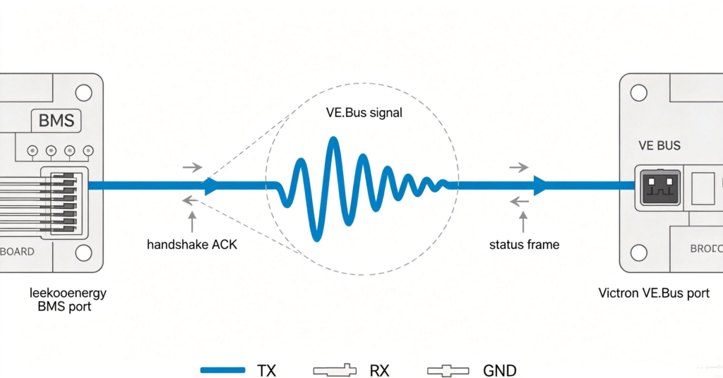
Many rack batteries – including leekooenergy-style racks – carry their own external BMS and expose digital contacts or CAN to the inverter. With Victron, the common path is to let the external BMS drive the safety contactor and feed Victron a clean allow/block signal plus cell data over CAN, while Victron manages charge voltage and current from the GX. The rule is one clear owner of the contactor: either Victron’s BMS or the rack BMS, not both fighting. Confirm the rack BMS’s contact output and CAN frame match what your Victron model expects before ordering, or the “plug-and-play” claim becomes a wiring weekend.
Q.Can a leekooenergy battery work with a Victron BMS?
Yes, where the leekooenergy pack BMS output matches Victron’s expected signaling for the chosen Victron model. Confirm the protocol match with both suppliers before ordering; the pack’s own protection remains the primary safety layer.
Q. What is the difference between VE.Bus BMS V2 and Lynx Smart BMS?
VE.Bus BMS V2 controls charge and load disconnect for smaller 48V systems; Lynx Smart BMS adds current measurement and monitoring within the Lynx bus for larger banks. Pick by system size and whether you use Lynx.
Q. Do I still need the pack’s own BMS?
Yes. The Victron BMS controls charge/throttle at the system level; the leekooenergy pack BMS does cell-level sensing and protection. Both layers are needed — one does not replace the other.
Q. Why does my Victron console show wrong state of charge?
Usually the battery monitor was not zero-calibrated, or charge limits differ between the pack and Victron side. Calibrate the monitor and align limits to the cell datasheet on both sides.
Q. Is Victron documentation enough, or do I need the pack manual?
Both. Victron manuals cover Victron hardware; the leekooenergy manual covers pack sensing, limits, and wiring. Integration needs the pack-side view this guide provides plus the official Victron sources.
Next step: confirm the protocol before you order
Send your Victron model to the battery supplier and get the protocol match in writing, then wire in the order above and test safe before load.
- See the leekooenergy BMS / battery product page (compatibility list)
- Read #28 BMS 101 to check connector and protocol
- ask the supplier for the Victron model compatibility certificate