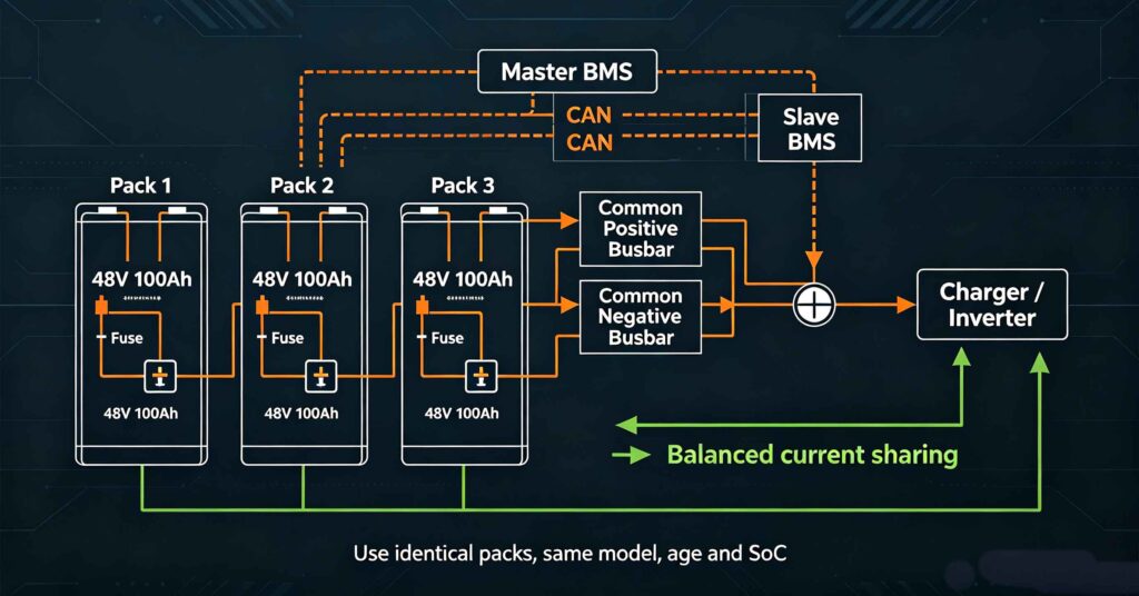
Parallel battery packs are multiple battery packs connected positive-to-positive and negative-to-negative to increase total capacity (Ah) and energy (kWh) while keeping the voltage the same. For example, three 48V 100Ah LiFePO4 packs in parallel form a 48V 300Ah (15.36 kWh) battery bank. Parallel connection is the standard method for scaling battery capacity beyond what a single pack can provide, but it introduces risks that do not exist with a single pack: circulating current between packs with different voltages, uneven current sharing, BMS coordination conflicts, and the potential for one pack to charge or discharge another pack uncontrollably. The key to safe parallel operation is matching the packs (same model, same age, same state of charge at connection), using individual fuses on each pack, coordinating the BMS units through a master-slave or CAN bus architecture, and ensuring balanced charging and discharging through proper system design.
When a single battery pack does not provide enough capacity for a project, the natural solution is to add another pack in parallel. This is how most residential, commercial and industrial battery banks are built — from two packs in a home backup system to dozens of packs in a utility-scale container. But parallel connection is not as simple as wiring positive to positive and negative to negative. Battery packs are not passive components like resistors — they are active chemical systems with their own battery management systems, and when they are connected together, they interact in ways that can cause problems if not properly managed. A parallel battery bank that is wired without proper voltage matching, fusing and BMS coordination can experience circulating currents that overheat connectors, cause uneven ageing, and in extreme cases create a safety hazard. This guide explains how parallel battery packs work, what can go wrong, and the best practices for safe and reliable parallel operation.
Parallel vs series: understanding the difference
Before discussing parallel connection, it is important to distinguish it from series connection, because the two serve different purposes and have different risks.
Series connection connects packs positive-to-negative, which adds the voltages while keeping the capacity the same. For example, four 12V 100Ah packs in series form a 48V 100Ah system. Series connection is used to build higher-voltage systems from lower-voltage packs. The primary risk in series connection is cell imbalance — if one pack or cell has lower capacity, it will reach full or empty before the others, and the BMS must protect it by shutting down the entire string.
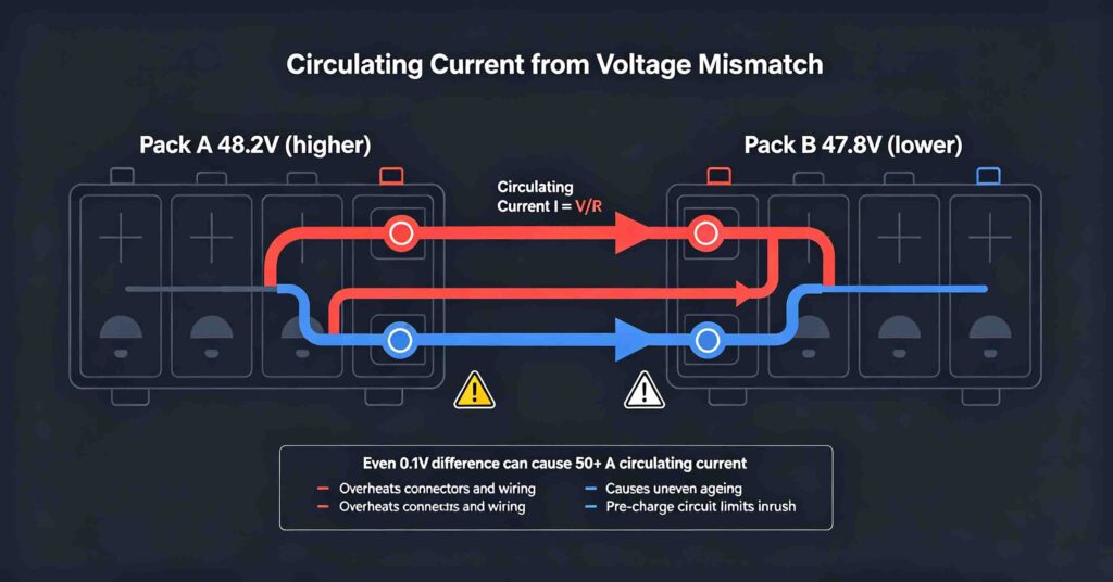
Parallel connection connects packs positive-to-positive and negative-to-negative, which adds the capacities while keeping the voltage the same. For example, three 48V 100Ah packs in parallel form a 48V 300Ah system. Parallel connection is used to build higher-capacity systems at the same voltage. The primary risk in parallel connection is circulating current — if one pack has a slightly higher voltage than another, current will flow from the higher-voltage pack to the lower-voltage pack, even when no load is connected. This circulating current can overheat connectors and wiring, cause uneven ageing, and in extreme cases damage the BMS or create a fire hazard.
Many large battery systems use a combination of series and parallel connection (often called “series-parallel” or “S-P” configuration): packs are connected in series to build the desired voltage, and these series strings are connected in parallel to build the desired capacity. For example, four 12V 100Ah packs in series form a 48V 100Ah string, and three such strings in parallel form a 48V 300Ah system. In a series-parallel configuration, both series imbalance and parallel circulating current risks must be managed.
What can go wrong: five risks of parallel battery packs
| Risk | Cause | Consequence | Prevention |
|---|---|---|---|
| 1. Circulating current | Voltage difference between parallel packs (even 0.1V can cause significant current) | Overheated connectors/wiring, uneven ageing, BMS damage, potential fire hazard | Match pack voltages within 0.05V before connecting; use identical packs; pre-charge circuit |
| 2. Uneven current sharing | Differences in internal resistance, cable length, or connector resistance between packs | One pack carries more current than others, causing uneven ageing and premature failure of the most-loaded pack | Use identical cable lengths and gauges; common busbar; matched packs; BMS current monitoring |
| 3. BMS coordination conflicts | Each pack’s BMS independently manages its own cells, without coordinating with other packs in parallel | One BMS may disconnect its pack while others continue, causing full load current to flow through remaining packs; charge/discharge instability | Master-slave BMS architecture or CAN bus coordination; parallel-compatible BMS design |
| 4. Charge imbalance | Packs with different capacities, ages, or internal resistance charge at different rates | One pack reaches full charge before others; its BMS may disconnect, leaving remaining packs to continue charging at higher current | Use identical packs (same model, capacity, age); balanced charging; BMS coordination |
| 5. Thermal runaway propagation | A fault in one pack (internal short, overcharge) causes it to overheat; adjacent packs in the same enclosure are exposed to the heat | Thermal runaway propagates from one pack to adjacent packs, escalating a single-pack fault to a system-level fire | Physical separation between packs; thermal barriers; fire suppression; individual fuses; BMS thermal protection |
The most common and most preventable risk is circulating current. When two battery packs are connected in parallel, current flows from the higher-voltage pack to the lower-voltage pack until their voltages equalise. If the voltage difference is small (a few hundredths of a volt), the circulating current is modest and will subside as the packs equalise. If the voltage difference is large (several tenths of a volt or more), the circulating current can be very high — potentially hundreds of amps — because the internal resistance of LiFePO4 packs is low. This high current can melt connectors, damage wiring, trip fuses, and in extreme cases cause a fire. The solution is to ensure that packs are at nearly identical voltages before connecting them, and to use a pre-charge circuit or a current-limiting connection process to equalise voltages gradually.
Seven best practices for safe parallel battery pack operation
- Use identical packs. All packs in a parallel bank should be the same model, same capacity, same voltage, same cell chemistry, and ideally from the same production batch. Packs of different ages, capacities or internal resistances will not share current evenly and will age at different rates. Never parallel a new pack with an old pack, or a high-capacity pack with a low-capacity pack.
- Match voltages before connecting. Before connecting packs in parallel, measure each pack’s open-circuit voltage and ensure they are within 0.05V (50mV) of each other. If the difference is larger, charge or discharge the packs individually until they match. This prevents large circulating currents at the moment of connection.
- Use a pre-charge circuit. For large battery banks, use a pre-charge circuit (a resistor in series with the connection) to gradually equalise voltages before making the full parallel connection. This limits the inrush current and protects connectors and BMS units from current spikes.
- Install individual fuses on each pack. Each pack in a parallel bank should have its own fuse on the positive (and ideally negative) terminal, rated to protect the pack’s wiring and connectors. The fuse should be located as close to the pack terminal as possible. If one pack develops an internal short, its fuse will blow, isolating it from the bank and preventing the other packs from discharging into the faulted pack.
- Use a common busbar with equal-length cables. Connect all packs to a common positive busbar and a common negative busbar, using cables of equal length and gauge for each pack. This ensures that the resistance in each pack’s connection path is the same, which promotes even current sharing. Avoid daisy-chaining packs (connecting pack 1 to pack 2 to pack 3), which creates unequal resistance paths and uneven current sharing.
- Use a master-slave BMS or parallel-compatible BMS. The BMS units in a parallel bank should be designed for parallel operation. This typically means a master-slave architecture where one BMS (the master) coordinates the charging and discharging of all packs, and the other BMS units (slaves) report cell data and execute the master’s commands. Alternatively, some BMS units use a CAN bus or other communication protocol to coordinate without a formal master-slave hierarchy. Never parallel packs with BMS units that are not designed for parallel operation — each BMS will independently try to manage its own pack, leading to conflicts and instability.
- Provide physical separation and thermal management. Packs in a parallel bank should be physically separated from each other with adequate spacing for airflow, and thermal barriers should be considered between packs to prevent thermal runaway propagation. The enclosure should be designed for adequate ventilation or active cooling to maintain all packs within their optimal temperature range. Regular thermal monitoring (via BMS temperature sensors) should be in place to detect abnormal temperature rise in any pack.
Q.Can I connect different LiFePO4 battery packs in parallel?
Technically yes, but it is not recommended. Packs of different models, capacities, ages, or internal resistances will not share current evenly — the pack with lower resistance carries more current, ages faster, and creates a vicious cycle of worsening imbalance. In extreme cases, a pack that reaches full charge first may have its BMS disconnect, leaving remaining packs to charge at higher current. If you must parallel different packs, use the same voltage and chemistry, match state of charge before connecting, use individual fuses, and monitor closely. Best practice: use identical packs from the same batch. For 48V system architecture details, see #35 48V lithium batteries explained.
Q.How many battery packs can I connect in parallel?
There is no hard theoretical limit, but practical limits depend on current sharing, BMS coordination, fusing, and thermal management. For small systems (residential, small commercial), 2–4 packs in parallel is common and straightforward. For larger systems, 8–16 packs may be used but requires robust master-slave BMS, high-current busbars, properly rated fuses, and adequate cooling. For utility-scale, packs are arranged in series-parallel within modular racks, with each rack having its own BMS and protection. As parallel count increases, design precision becomes critical — 2 packs tolerate sloppiness; 16 do not.
Q.Do I need a BMS on each battery pack in a parallel bank?
Yes. Each pack needs its own BMS to protect its cells from overcharge, overdischarge, overcurrent, and over-temperature — this protection is needed regardless of parallel operation. In a parallel bank, the BMS units must be designed for parallel operation (typically master-slave architecture or CAN bus coordination). A common mistake is using standalone BMS units in parallel, where each independently manages its pack without coordination. This can cause cascading failures: one BMS disconnects, full current flows through remaining packs, their BMS disconnect too. Always use parallel-compatible BMS.
Q.What size fuse do I need for each parallel battery pack?
The fuse should be rated 1.25–1.5× the pack’s maximum continuous discharge current. For example, a 48V 100Ah pack with 100A max discharge uses a 125A or 150A fuse. The fuse must be DC-rated, rated for the system’s maximum DC voltage, and located close to the pack’s positive terminal. It must also have sufficient interrupting capacity — in a parallel bank, all packs can discharge into a fault simultaneously, so fault current can be very high. Consult the manufacturer and a qualified electrical engineer.
Q.How do I prevent circulating current between parallel battery packs?
Circulating current is caused by voltage differences between packs. Prevent it with: (1) identical packs (same model, capacity, age, resistance); (2) match all packs to within 0.05V before connecting; (3) use a pre-charge circuit to gradually equalize voltages, avoiding inrush current; (4) use master-slave or parallel-compatible BMS that coordinates charging across all packs; (5) use equal-length cables and a common busbar. With these measures, circulating current stays below 1% of rated current.
Next step: design your parallel battery bank with safety built in
Parallel battery packs are the standard way to scale capacity, but they are not a set-it-and-forget-it solution. A well-designed parallel bank — with identical packs, matched voltages, individual fuses, equal-length cabling, a master-slave BMS, and proper thermal management — will operate reliably for thousands of cycles. A poorly designed parallel bank — with mismatched packs, no fuses, daisy-chained wiring, and uncoordinated BMS units — will experience circulating currents, uneven ageing, and potentially dangerous faults. The difference is in the design.
- Read the complete LiFePO4 guide in #1 LiFePO4 batteries complete guide
- Understand 48V system architecture in #35 48V lithium batteries explained
- Review battery cost considerations in #7 how much does a solar battery cost
- See the OEM/ODM custom pack process in #20 custom battery pack OEM/ODM
- Ask leekooenergy for a parallel battery bank design specification that includes: recommended pack model and quantity for your target capacity and voltage, BMS architecture (master-slave or CAN bus coordination) for parallel operation, fuse sizing and placement for each pack, cable gauge and length recommendations for equal current sharing, busbar specifications, pre-charge circuit design, thermal management requirements (spacing, ventilation, cooling), and a step-by-step commissioning procedure (voltage matching, pre-charge, parallel connection, BMS configuration) — so your parallel battery bank is designed for safe, reliable and balanced operation from day one