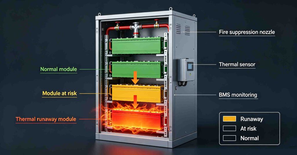
Battery thermal runaway is a self-accelerating chain reaction in which a lithium-ion cell releases heat faster than it can dissipate, causing the cell temperature to rise rapidly, the electrolyte to break down, and flammable gas to vent — potentially igniting and propagating to adjacent cells. In a battery energy storage system (BESS), the risk is managed through a layered approach: cell chemistry selection (LiFePO4 is thermally more stable than NMC/NCA), battery management system (BMS) protection, thermal management, physical separation, gas and smoke detection, and a fire suppression system designed for the specific installation. NFPA 855 is the U.S. installation standard that sets minimum requirements for energy storage system siting, spacing, ventilation, fire protection and emergency response. Compliance with NFPA 855 depends on the complete system design, the installation environment and the authority having jurisdiction (AHJ) — a product certification alone does not guarantee installation-level compliance.
Battery safety is no longer a footnote in energy storage procurement. It is a gating requirement: insurers ask for it, fire marshals enforce it, and tender documents increasingly specify UL 9540, UL 9540A and NFPA 855 compliance as preconditions for bidding. Yet the terminology around battery thermal runaway, fire suppression and standards compliance is often used loosely — sometimes by vendors who benefit from the ambiguity. This guide explains what thermal runaway actually is, how it spreads inside a battery rack, what fire suppression systems can and cannot do, what NFPA 855 requires at the installation level, and how UL 9540 and UL 9540A fit into the compliance picture. It is written for the facility owner, safety engineer and EPC project manager who needs to specify safety requirements accurately rather than rely on marketing claims.
The broader BESS safety and fire code overview is in #44 BESS fires & energy storage safety codes; the BMS electronic protection layer is in #49 BMS protection: overcharge, overdischarge & thermal; the thermal management comparison (liquid vs air cooling) is in #36 liquid cooling vs air cooling for C&I BESS. This article stays on thermal runaway mechanics, fire suppression and standards.
What battery thermal runaway is — and the three stages that matter
Thermal runaway begins when a cell’s internal temperature reaches the point at which exothermic (heat-releasing) chemical reactions inside the cell generate more heat than the cell can dissipate to its surroundings. Once that threshold is crossed, the temperature rise accelerates: more heat drives faster reactions, faster reactions release more heat, and the cycle feeds on itself. The trigger can be an internal short circuit (from a manufacturing defect or physical damage), an external short circuit, overcharge, overdischarge, exposure to external heat, or mechanical penetration. In a well-designed BESS, the BMS is intended to prevent the electrical triggers (overcharge, overdischarge, external short) before the cell reaches the thermal runaway threshold.
The process unfolds in three stages, and the distinction matters because each stage requires a different response:
- Stage 1 — Onset and gas venting. The cell temperature rises, the electrolyte begins to decompose, and the cell’s internal pressure increases. At a defined pressure threshold, the cell vent opens and flammable gas (a mixture of hydrogen, methane, ethylene and other hydrocarbons, depending on chemistry) is released. At this stage there may be no flame — only gas. Gas detection is the earliest warning available.
- Stage 2 — Ignition and combustion. If the vented gas encounters an ignition source (a spark, a hot surface, or the high temperature of the failing cell itself), it ignites. The cell may produce a jet flame from the vent. The cell temperature continues to rise, potentially reaching several hundred degrees Celsius. At this stage, the fire is fuelled by the cell’s own electrolyte and electrode materials — not by an external fuel source.
- Stage 3 — Propagation. The heat from the failing cell transfers to adjacent cells through conduction (cell-to-cell contact), convection (hot gas flow) and radiation. If the adjacent cells reach their own thermal runaway thresholds, they also enter runaway, and the process cascades through the module, the rack and potentially the container. Propagation is the stage that turns a single-cell fault into a system-level fire event. UL 9540A testing is specifically designed to evaluate whether a system can prevent or limit propagation.
A critical fact that many non-specialist buyers miss: a lithium-ion battery fire is not a conventional fuel fire. The cell carries its own oxidiser in the cathode material, which means that depriving the fire of external oxygen (as a gas-based clean-agent suppression system does) does not necessarily stop the combustion. The cell can continue to burn from within until its reactive materials are consumed. This is why fire suppression for BESS is more complex than suppressing a fire in a conventional electrical room.
How battery thermal runaway propagates through a battery rack
Understanding propagation requires looking at the physical layout of a BESS. A typical system is built in layers: a cell is grouped with other cells into a module; modules are grouped into a rack; racks are grouped into a container or room. Thermal runaway can propagate at every layer, and the design of each layer determines whether propagation is prevented, limited, or allowed to proceed.
At the cell-to-module level, propagation depends on cell spacing, the presence of thermal barriers (microporous insulation, ceramic blankets, intumescent pads), and the thermal conductivity of the module structure. Cylindrical cells (18650, 21700) have natural spacing between cells but are often packed tightly in modules. Prismatic and pouch cells have large flat surfaces in direct contact, which makes conductive heat transfer more efficient — and makes thermal barriers more important. Pouch cells also swell during thermal runaway, which can physically damage adjacent cells.
At the module-to-rack level, propagation depends on whether modules are physically separated, whether there is a fire-resistant barrier between modules, and whether the rack design directs vented gas away from adjacent modules rather than trapping it. A well-designed rack may include a gas plenum that collects vented gas and directs it to an exhaust or a suppression nozzle, rather than allowing it to pool around other modules.
At the rack-to-container level, propagation depends on container ventilation, fire barriers between racks, and the capacity of the fire suppression system to act across multiple racks. NFPA 855 addresses this level through requirements for spacing, separation and fire protection — which are covered in the NFPA 855 section below.
Fire suppression for battery energy storage: what works, what doesn’t
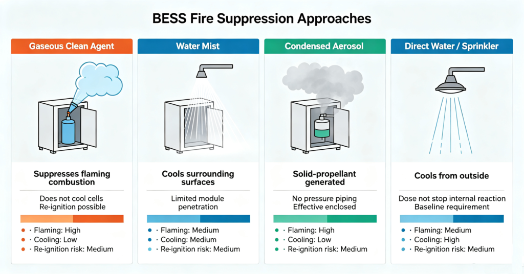
There is no single fire suppression technology that solves all stages of a lithium-ion battery event. The most effective BESS installations use a layered approach: early gas detection to trigger ventilation and shutdown, a suppression system to address flaming combustion and limit spread, and structural separation to prevent propagation to adjacent systems. The table below summarises the four main suppression approaches used in BESS installations, their mechanisms, and their limitations.
| Suppression type | Mechanism | Effective against | Limitations |
|---|---|---|---|
| Gaseous clean agent (FK-5-1-12, Novec 1230, IG-55, IG-100) | Displaces oxygen and interrupts chemical combustion chain | Flaming combustion in the enclosed space; gas-phase ignition prevention | Does not cool the cell; does not stop internal exothermic reactions; re-ignition possible if the cell continues to vent flammable gas; requires tight enclosure integrity |
| Water mist (high-pressure or low-pressure fine droplet systems) | Cools surfaces and displaces oxygen through steam expansion; absorbs radiant heat | Surface cooling; suppression of flaming combustion outside the cell; limiting spread to adjacent racks | Limited penetration into sealed battery modules; does not stop the internal cell reaction; may not prevent re-ignition from a cell still in runaway |
| Condensed aerosol (solid-propellant aerosol generators) | Releases fine potassium-based aerosol particles that interrupt combustion chemistry; no pressurised piping | Flaming combustion in enclosed spaces; gas-phase suppression; suitable for small enclosures where piping is impractical | Does not cool the cell; aerosol residue may require cleanup; effectiveness depends on enclosure volume and generator placement; not typically used as the sole suppression in large containers |
| Direct water / sprinkler (standard ESFR or control-mode sprinklers) | Cools from outside the battery enclosure; wets surrounding combustibles; controls fire spread to the building | Building-level fire control; cooling of container exteriors; preventing fire spread to adjacent structures | Does not penetrate sealed battery modules; does not stop internal cell thermal runaway; may be required by AHJ as a baseline even when an additional BESS-specific system is installed |
The key takeaway is that no suppression system “stops” thermal runaway inside a cell. Once a cell has entered Stage 2 or Stage 3, the internal reactions will continue until the reactive materials are consumed — which can take hours for a large-format prismatic cell. The realistic goals of suppression are: (1) prevent ignition of vented gas at Stage 1, (2) suppress flaming combustion at Stage 2 to limit damage and protect emergency responders, and (3) prevent or delay propagation at Stage 3 to contain the event to a single module or rack. The most effective installations combine early gas detection (which can trigger shutdown and ventilation before ignition), a BESS-specific suppression system, and structural separation between racks or containers.
NFPA 855: what the installation standard actually requires
NFPA 855, Standard for the Installation of Stationary Energy Storage Systems is the U.S. standard that governs how stationary battery energy storage systems are installed, sited and protected. It is not a product standard — it does not certify individual batteries or systems. It sets minimum requirements for the installation environment, and compliance is enforced by the authority having jurisdiction (AHJ), typically the local fire marshal or building official. The standard is periodically updated; buyers should confirm which edition the AHJ has adopted.
The areas of NFPA 855 that most directly affect a BESS procurement and installation include:
- Siting and spacing. The standard specifies minimum separation distances between energy storage systems and property lines, buildings, fire department access roads, and other exposures. The required distances depend on the system size (kWh), the battery chemistry, and whether the system is indoors or outdoors. Larger systems and higher-energy chemistries generally require greater separation.
- Indoor installation requirements. For systems installed inside buildings, NFPA 855 sets requirements for room construction (fire-resistance ratings), egress, spill control (for lead-acid and flow batteries), ventilation, and detection. Lithium-ion systems have specific requirements related to gas detection and thermal runaway mitigation.
- Fire protection. The standard specifies fire suppression requirements based on system size and chemistry. For lithium-ion systems above certain size thresholds, a listed fire suppression system or an engineered equivalent may be required. The standard also addresses sprinkler design criteria for battery rooms.
- Ventilation and gas management. Because lithium-ion cells in thermal runaway vent flammable gas, NFPA 855 addresses ventilation requirements for indoor installations to prevent gas accumulation. The specific ventilation rate depends on the system size and the AHJ’s interpretation.
- Identification and signage. The standard requires signage identifying the energy storage system, its chemistry, its voltage, and emergency response information. This is intended to help first responders identify the hazard before entering the space.
- Emergency response and disconnect. Requirements for emergency disconnect (EPO) switches, lockout/tagout, and isolation of the battery system from the electrical supply are specified to protect emergency responders and maintenance personnel.
Buyers should be aware that NFPA 855 compliance is installation-specific. A system that is listed to UL 9540 (a product standard) is not automatically compliant with NFPA 855 at a given site — the installation must also meet the siting, spacing, ventilation and fire protection requirements of the standard, as interpreted by the AHJ. Procurement teams should engage the AHJ early in the project, ideally before selecting a system, to confirm which edition of NFPA 855 applies and what additional local requirements may exist.
UL 9540 and UL 9540A: product certification vs thermal runaway testing
UL 9540 and UL 9540A are often mentioned together, but they serve different purposes, and confusing them is a common procurement error.
UL 9540, Standard for Energy Storage Systems and Equipment, is a product safety standard that evaluates the complete energy storage system (battery, BMS, inverter, interconnects, enclosure) for electrical safety, fire safety, and mechanical safety under normal and fault conditions. A system that is listed to UL 9540 has been evaluated by a Nationally Recognized Testing Laboratory (NRTL) and found to meet the standard’s requirements. UL 9540 listing is increasingly required by AHJs, insurers and tender documents as a baseline qualification.
UL 9540A, Test Method for Evaluating Thermal Runaway Fire Propagation in Battery Energy Storage Systems, is a test method — not a certification standard. It defines a procedure for inducing thermal runaway in a single cell within a system and measuring whether and how the event propagates to adjacent cells, modules and racks. The test produces data that manufacturers use to demonstrate propagation resistance, and that AHJs use to evaluate whether a system can be installed without additional fire protection or with reduced separation distances. UL 9540A testing is performed at the cell, module and unit (rack/container) levels; a system that passes at the unit level demonstrates that a single-cell thermal runaway does not propagate to the point of causing a system-level fire event.
The distinction matters in procurement because a vendor may claim “UL 9540A tested” without specifying the level (cell vs module vs unit) or the test outcome. A cell-level test does not demonstrate that the rack will resist propagation. Buyers should request the full UL 9540A test report, including the test level, the test configuration, the number of cells induced into runaway, and whether propagation occurred. The report should be from an NRTL or an accredited testing laboratory.
Installation safety checklist: what to verify before energising a BESS
The following checklist covers the safety-related items that a facility owner or EPC should verify before a battery energy storage system is energised and handed over to operations. It is not a substitute for a professional fire protection engineering review or an AHJ inspection, but it covers the items that most commonly cause delays or rework.
- System certification. Confirm that the complete energy storage system (not just the battery module) is listed to UL 9540 by an NRTL. Request the certificate and confirm that the system configuration delivered matches the configuration listed.
- Thermal runaway test data. Request the UL 9540A test report at the highest level tested (module or unit). Confirm that the test configuration matches the delivered configuration and that propagation was limited or prevented.
- Siting and spacing. Verify that the installed location meets the NFPA 855 separation distances to property lines, buildings, exposures and fire department access. Confirm that the AHJ has reviewed and accepted the siting.
- Fire suppression. Confirm that the installed fire suppression system matches the design specified in the fire protection engineering report and that it has been inspected and tagged. Verify that the suppression system is compatible with the battery chemistry and the enclosure design.
- Gas detection. For indoor lithium-ion installations, confirm that gas detection (hydrogen and/or VOC) is installed, calibrated, and interlocked with ventilation shutdown and audible/visual alarms. Verify that the detection setpoints are based on the manufacturer’s recommendations and the AHJ’s requirements.
- Ventilation. Confirm that the ventilation system meets the required airflow rate, that it is interlocked with gas detection, and that exhaust is directed to a safe location away from air intakes and ignition sources.
- Emergency disconnect. Verify that the emergency power-off (EPO) switch is accessible, clearly labelled, and tested. Confirm that it disconnects the battery system from the inverter/PCS and that the battery itself enters a safe state.
- Signage and identification. Confirm that the system is labelled with chemistry (LiFePO4), nominal voltage, capacity (kWh), emergency contact information, and any hazard warnings required by NFPA 855 and local codes.
- Thermal management. Verify that the battery cooling system (air or liquid) is operational, that temperature sensors are calibrated, and that the BMS high-temperature alarms and derating thresholds are configured per the manufacturer’s specification.
- Operations and maintenance documentation. Confirm that the owner has received the operation and maintenance manual, the emergency response guide, the single-line diagram, and the as-built drawings. Verify that operations personnel have been trained on normal operation, emergency shutdown, and the procedure for responding to a thermal runaway alarm.
Q. What causes battery thermal runaway?
Battery thermal runaway is caused by any condition that raises a lithium-ion cell’s internal temperature to the point where exothermic chemical reactions inside the cell generate heat faster than it can dissipate. Common triggers include internal short circuits (from manufacturing defects, physical damage, or dendrite growth), external short circuits, overcharge (charging beyond the cell’s upper voltage limit), overdischarge (which can damage the anode current collector), exposure to external heat (from a fire or a failing adjacent cell), and mechanical penetration. In a properly designed energy storage system, the battery management system is intended to prevent the electrical triggers — overcharge, overdischarge and external short — before the cell reaches the thermal runaway threshold.
Q. Can fire suppression stop a lithium-ion battery fire?
Fire suppression can suppress the flaming combustion and limit the spread of a lithium-ion battery fire, but it cannot stop the internal thermal runaway reaction inside a cell that has already entered Stage 2 or Stage 3. The cell carries its own oxidiser in the cathode material, so depriving the fire of external oxygen does not halt the internal reactions — the cell will continue to generate heat and vent flammable gas until its reactive materials are consumed, which can take hours. The realistic goals of a BESS fire suppression system are: (1) prevent ignition of vented gas through early detection and gas-phase suppression, (2) suppress flaming combustion to protect emergency responders and limit damage, and (3) prevent or delay propagation to adjacent modules and racks through cooling and structural separation. No single suppression technology achieves all three; a layered approach is required.
Q. What is the difference between UL 9540 and UL 9540A?
UL 9540 is a product safety standard that evaluates the complete energy storage system — battery, BMS, inverter, enclosure and interconnects — for electrical safety, fire safety and mechanical safety. A system listed to UL 9540 has been certified by a Nationally Recognized Testing Laboratory as meeting the standard’s requirements. UL 9540A is a test method, not a certification standard: it defines a procedure for inducing thermal runaway in a single cell and measuring whether and how the event propagates to adjacent cells, modules and the full unit. UL 9540A testing produces data that demonstrates propagation resistance; it is performed at cell, module and unit levels. A system may be UL 9540 listed without having undergone UL 9540A testing, and a system that has undergone UL 9540A testing at the cell level has not necessarily demonstrated rack-level propagation resistance. Buyers should request both the UL 9540 listing certificate and the full UL 9540A test report at the highest level tested.
Q. Does NFPA 855 require a fire suppression system for all battery storage?
NFPA 855 requires fire protection for stationary energy storage systems based on the system size, chemistry and installation location — not a blanket requirement for every installation. Small systems below certain energy thresholds (the specific thresholds vary by edition and chemistry) may be exempt from dedicated fire suppression requirements, though they are still subject to siting, identification and disconnect requirements. For lithium-ion systems above the threshold, the standard typically requires a listed fire suppression system or an engineered equivalent, along with detection and ventilation for indoor installations. The specific requirements are enforced by the authority having jurisdiction (AHJ), which may adopt a particular edition of NFPA 855 and may impose additional local requirements. Buyers should engage the AHJ early in the project to confirm the applicable requirements rather than assuming that a product certification or a vendor’s claim of “NFPA 855 compliant” covers the installation.
Q. Is LiFePO4 safer than NMC for thermal runaway?
LiFePO4 (lithium iron phosphate) chemistry is inherently more thermally stable than NMC (lithium nickel manganese cobalt oxide) and NCA (lithium nickel cobalt aluminium oxide). The LiFePO4 cathode does not release oxygen at elevated temperatures in the same way that NMC/NCA cathodes do, which means that a LiFePO4 cell in thermal runaway is less likely to produce a self-sustaining flame and is less prone to violent propagation. The thermal runaway onset temperature for LiFePO4 is also typically higher than for NMC. However, “more thermally stable” does not mean “immune to thermal runaway”: a LiFePO4 cell that is physically damaged, overcharged, or exposed to sufficient external heat can still enter thermal runaway and vent flammable gas. This is why LiFePO4 systems still require BMS protection, thermal management, gas detection and fire suppression — the chemistry reduces the probability and severity of thermal runaway, but it does not eliminate the need for system-level safety design. Buyers should not accept “LiFePO4 is safe” as a substitute for UL 9540 listing, UL 9540A test data, and NFPA 855-compliant installation.
Next step: specify safety requirements before you specify the battery
Battery safety is a system-level property, not a checkbox on a datasheet. The cell chemistry, the BMS, the thermal management, the enclosure, the fire suppression, the gas detection, the ventilation and the installation siting all contribute to the actual safety performance of the installed system. Specifying any one of them in isolation — or accepting a vendor’s marketing claim of “safe” or “compliant” without documentation — leaves gaps that the AHJ, the insurer and the emergency responders will eventually find.
- Read the broader BESS safety and fire code overview in #44 BESS fires & energy storage safety codes
- Understand the BMS electronic protection layer in #49 BMS protection: overcharge, overdischarge & thermal
- Compare liquid vs air cooling thermal management in #36 liquid cooling vs air cooling for C&I BESS
- Review the BESS components and system architecture in #52 BESS components: battery, PCS, BMS & EMS
- Ask leekooenergy for a safety specification package that includes: the UL 9540 listing certificate for the complete system (not just the module), the full UL 9540A test report at the unit level with test configuration and propagation outcome, the BMS protection threshold settings, the thermal management design, the gas detection and fire suppression interface specifications, and the NFPA 855 installation guidance document — so your procurement team, your fire protection engineer and your AHJ are all working from the same documented safety baseline