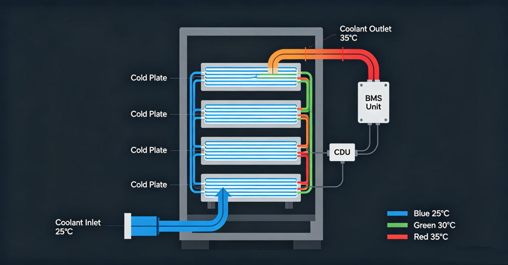
A liquid cooled BESS (battery energy storage system) uses a circulating coolant — typically a water-glycol mixture or a dielectric fluid — to remove heat from battery cells through cold plates or immersion, rather than relying on forced air. The charge/discharge rate, measured in C-rate, directly affects both cycle life and thermal load: a system operated at 0.5C (full charge or discharge in 2 hours) generates roughly half the heat of the same system at 1C (full charge or discharge in 1 hour), and the lower heat rate translates to lower cell temperatures, smaller temperature gradients, and significantly longer cycle life. Liquid cooling becomes necessary when a BESS is operated at or above 0.5C continuously, when cell temperatures must be maintained within a narrow band (typically 20–30°C) for maximum cycle life, or when the system is deployed in a high-ambient-temperature environment where air cooling cannot maintain the required temperature.
The C-rate is one of the most underrated specifications on a BESS datasheet. It looks like a simple number — 0.5C, 1C, 2C — but it determines how much heat the cells generate, how large the cooling system must be, how quickly the battery degrades, and ultimately how many cycles the system delivers before reaching end of life. A system specified at 0.5C but operated at 1C will not only run hotter; it will degrade faster and may void the warranty if the continuous discharge rate exceeds the rated value. This guide explains how C-rate and thermal design interact in liquid-cooled BESS, what the 0.5C vs 1C decision means for cycle life and cost, and how to specify a liquid cooling system that matches the actual duty cycle.
The broader liquid-vs-air cooling comparison is in #36 liquid cooling vs air cooling for C&I BESS; the industrial and commercial storage applications are in #15 industrial battery storage; the utility-scale perspective is in #22 utility-scale battery storage. This article stays on the liquid-cooled system itself: the C-rate question, the thermal architecture, and the coolant selection.
What C-rate means — and why it drives the thermal design
C-rate is a measure of how fast a battery is charged or discharged relative to its rated capacity. A 100 kWh battery discharged at 1C delivers 100 kW of power and is fully discharged in 1 hour. The same battery at 0.5C delivers 50 kW and takes 2 hours to discharge. At 2C, it delivers 200 kW and is discharged in 30 minutes. The C-rate is not just a power specification — it is a heat generation specification.
Every lithium-ion cell has an internal resistance. When current flows through that resistance, heat is generated according to Joule’s law: heat equals current squared times resistance (I²R). Because current is directly proportional to C-rate, doubling the C-rate roughly quadruples the resistive heat generation. There is also a reversible heat component associated with the electrochemical reactions themselves, which increases with C-rate but is less dramatic than the I²R component. The net effect is that a 1C system generates significantly more heat per unit time than a 0.5C system, and the cooling system must be sized to remove that heat while keeping the cells within their optimal temperature range.
0.5C vs 1C: how the rate affects cycle life, temperature and cost
The choice between 0.5C and 1C is not simply a matter of “more power is better.” It is a system-level trade-off that affects cycle life, cooling system size, footprint, capital cost and operating cost. The table below summarises the key differences for a typical LiFePO4 BESS.
| Parameter | 0.5C system | 1C system | Implication |
|---|---|---|---|
| Full discharge time | 2 hours | 1 hour | 1C delivers twice the power from the same energy capacity |
| Heat generation (relative) | ~1× baseline | ~3–4× baseline | I²R heating dominates; 1C requires significantly more cooling capacity |
| Typical cell temperature rise | 3–5°C above ambient | 8–15°C above ambient | Higher temperatures accelerate degradation; 1C needs active cooling to stay in range |
| Cycle life (to 80% SoH) | 8,000–10,000+ cycles | 5,000–7,000 cycles | Lower C-rate and lower operating temperature extend cycle life by 30–50% |
| Cooling system size | Smaller CDU, lower flow rate | Larger CDU, higher flow rate, larger heat exchanger | 1C cooling system can add 10–20% to system cost |
| Footprint | More kWh per m² (less cooling hardware) | Less kWh per m² (more cooling hardware) | Space-constrained sites may prefer 0.5C |
| Typical applications | Energy shifting, peak shaving (2–4h duration), frequency regulation (duty-cycled) | Fast frequency response, UPS/backup, high-power ramp applications, 1h duration | Match C-rate to the application; don’t over-specify power |
| Levelised cost of storage (LCOS) | Lower for long-duration applications | Lower for short-duration, high-power applications | The optimal C-rate depends on the revenue stack and duty cycle |
The cycle-life difference deserves emphasis. A LiFePO4 cell operated at 0.5C with good thermal management (cell temperature maintained at 25±5°C, temperature gradient across the pack below 5°C) can reasonably be expected to reach 8,000–10,000 cycles before degrading to 80% of its original capacity. The same cell operated at 1C continuous, even with liquid cooling, will typically run 5–10°C warmer and may reach 5,000–7,000 cycles. Over a 15-year project life, that difference translates to whether the battery needs replacement once or not at all — a decision that can change the project’s internal rate of return by several percentage points.
Liquid cooling architecture: cold plates, immersion and coolant distribution
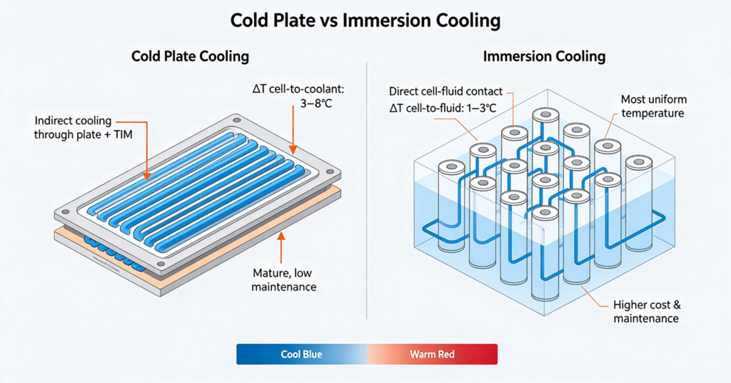
Liquid cooling for BESS comes in two primary architectures: indirect cooling (cold plates) and direct cooling (immersion). Each has different thermal performance, complexity, cost and maintenance requirements.
Cold plate cooling is the most common architecture in a liquid cooled BESS today. Thin metal plates (typically aluminium) with internal coolant channels are placed in direct thermal contact with the battery cells or modules — either between cells, on the sides of modules, or under the module. The coolant flows through the channels, absorbing heat through the plate wall. Cold plate cooling is mature, reliable, and relatively easy to maintain. Its limitation is that it cools the cells indirectly through the plate and any thermal interface material, which creates a temperature gradient between the coolant and the cell core. For most C&I BESS applications at up to 1C, cold plate cooling is sufficient and cost-effective.
Immersion cooling submerges the battery cells directly in a dielectric (electrically non-conductive) fluid. The fluid contacts the cell surfaces directly, eliminating the thermal interface resistance of cold plates. Immersion cooling provides the most uniform cell temperatures and the highest heat removal capacity, making it suitable for high-C-rate systems (1C+), high-ambient-temperature deployments, and applications where maximum cycle life is critical. The trade-offs are higher upfront cost (specialised fluid, sealed tank, fluid handling), higher maintenance complexity (fluid degradation monitoring, filtration), and the fact that the technology is less mature in the BESS market than cold plate cooling.
In a liquid cooled BESS, both architectures require a coolant distribution unit (CDU) — the mechanical assembly that circulates the coolant, regulates its temperature through a heat exchanger or chiller, and maintains system pressure. For background on thermal management standards, see the. The CDU includes pumps, a heat exchanger (air-cooled or water-cooled), a heater (for cold-ambient warm-up), filters, sensors (temperature, pressure, flow, conductivity), and a control interface to the BMS. The CDU is typically the most maintenance-intensive component of a liquid-cooled BESS and should be designed for easy access and component replacement.
Coolant selection: water-glycol, dielectric fluids and the maintenance question
The coolant is the working fluid that carries heat from the cells to the heat exchanger. The choice of coolant affects thermal performance, corrosion risk, maintenance frequency, safety and cost. For cold plate systems, the most common coolant is a mixture of deionised water and ethylene glycol or propylene glycol, typically in a 50/50 or 60/40 ratio. Water provides excellent heat capacity and thermal conductivity; the glycol lowers the freezing point and provides corrosion inhibition. The mixture must be maintained at the correct concentration — too much glycol reduces heat transfer, too little risks freezing in cold climates.
For immersion systems, the coolant must be dielectric (electrically non-conductive) because it is in direct contact with live cell terminals and busbars. Common dielectric fluids include synthetic hydrocarbons, ester-based fluids, and fluorinated fluids. Dielectric fluids have lower heat capacity and thermal conductivity than water-glycol, which means higher flow rates are needed to achieve the same heat removal. They also degrade over time through oxidation and moisture absorption, requiring periodic monitoring of viscosity, acidity and dielectric strength. The cost of dielectric fluid is significantly higher than water-glycol — sometimes by an order of magnitude — which is a factor in the total cost of ownership of an immersion-cooled system.
Regardless of coolant type, three maintenance items are critical: (1) concentration and quality monitoring — test the coolant annually for glycol concentration, pH, conductivity and inhibitor levels; (2) filtration — replace coolant filters according to the manufacturer’s schedule to prevent particulate buildup in the cold plate channels; (3) leak detection — monitor system pressure and coolant level; a slow leak in a cold plate system can lead to air entrainment, reduced cooling performance, and eventual pump damage. For immersion systems, leak detection is even more critical because the dielectric fluid is expensive and can be hazardous if it contacts incompatible materials.
When to choose liquid cooling — and when air cooling is enough
Liquid cooling is not always the right choice. It adds cost, complexity and maintenance. The decision should be based on the actual duty cycle, the ambient environment, and the required cycle life. Use this checklist to determine whether liquid cooling is necessary for a given project:
- Continuous C-rate at or above 0.5C. If the system will be charged or discharged at 0.5C or higher for extended periods (more than 30 minutes continuously), air cooling may not maintain cell temperatures within the optimal range, and liquid cooling should be considered.
- High ambient temperature. If the system is deployed in a location where ambient temperatures regularly exceed 35°C, air cooling becomes less effective because the temperature difference between the air and the cells is small. Liquid cooling can maintain cell temperatures even in high-ambient environments.
- High cycle life requirement. If the project business case depends on 8,000+ cycles (typical for frequency regulation or daily energy shifting), maintaining tight temperature control is critical, and liquid cooling provides the most uniform cell temperatures.
- Space-constrained indoor deployment. If the system must be installed indoors with limited space for air handling, liquid cooling can provide higher energy density per square metre because it does not require large air plenums or fan arrays.
- Low C-rate, mild climate, long-duration application. If the system operates at 0.25C or lower, in a climate where ambient temperatures are between 10–30°C year-round, and the application is long-duration energy shifting (4+ hours), air cooling may be sufficient and more cost-effective. The lower heat generation rate means air can remove the heat without excessive cell temperature rise.
The most common mistake in BESS procurement is specifying liquid cooling because it is “premium” or “advanced” without evaluating whether the actual duty cycle requires it. Conversely, specifying air cooling for a 1C frequency regulation application in a hot climate is a recipe for premature degradation and potential warranty issues. The right approach is to model the actual duty cycle — including charge/discharge rates, duration, frequency and ambient temperature — and size the cooling system to maintain cell temperatures within the manufacturer’s specified range under all operating conditions.
Q. What is the difference between 0.5C and 1C in a BESS?
C-rate measures how fast a battery is charged or discharged relative to its capacity. A 100 kWh battery at 0.5C delivers 50 kW and takes 2 hours to fully discharge; at 1C it delivers 100 kW and takes 1 hour. The practical difference is heat generation and cycle life: because resistive heating increases with the square of current, a 1C system generates roughly 3–4 times the heat of a 0.5C system, runs 5–10°C warmer, and typically achieves 30–50% fewer cycles before reaching end of life. A 0.5C system is suitable for 2–4 hour energy shifting and peak shaving; a 1C system is needed for fast frequency response, UPS backup and high-power ramp applications.
Q. Does liquid cooling extend battery cycle life?
Yes, when it maintains cell temperatures within the optimal range (typically 20–30°C for LiFePO4) and minimises temperature gradients across the pack. Lithium-ion degradation accelerates exponentially with temperature — a cell operating at 35°C degrades roughly twice as fast as the same cell at 25°C. Liquid cooling provides more uniform cell temperatures than air cooling, especially at high C-rates, which reduces the spread of degradation across the pack and extends the system-level cycle life. The magnitude of the extension depends on the C-rate and ambient conditions: at 0.5C in a mild climate, the difference may be 10–20%; at 1C in a hot climate, it can be 30–50%.
Q. What coolant is used in liquid cooled BESS?
For cold plate (indirect) cooling systems, the most common coolant is a mixture of deionised water and ethylene glycol or propylene glycol, typically 50/50 or 60/40 by volume. The water provides high heat capacity and thermal conductivity; the glycol lowers the freezing point and provides corrosion inhibition. For immersion (direct) cooling systems, the coolant must be dielectric (electrically non-conductive) because it contacts live cell terminals; common types include synthetic hydrocarbons, ester-based fluids and fluorinated fluids. Dielectric fluids have lower thermal performance than water-glycol and are significantly more expensive, but they provide the most uniform cell cooling. The coolant should be tested annually for concentration, pH, conductivity and inhibitor levels, and filters should be replaced per the manufacturer’s schedule.
Q. Is immersion cooling better than cold plate cooling?
Immersion cooling provides better thermal performance — more uniform cell temperatures, lower cell-to-coolant thermal resistance, and higher heat removal capacity — but it is not always “better” in a total-cost sense. Cold plate cooling is more mature, lower cost, easier to maintain, and sufficient for most C&I BESS applications up to 1C. Immersion cooling is advantageous for high-C-rate systems (1C+), high-ambient-temperature deployments, and applications where maximum cycle life and uniform cell temperatures are critical. The decision should be based on the duty cycle, the ambient environment, the required cycle life, and the total cost of ownership — including coolant replacement, maintenance labour, and the higher upfront cost of the immersion system.
Q. When is air cooling sufficient for a BESS?
Air cooling is sufficient when the system operates at a low C-rate (typically 0.25C or lower continuously), in a mild climate where ambient temperatures stay between 10–30°C, and for long-duration applications (4+ hours) where the heat generation rate is low enough that forced air can remove it without excessive cell temperature rise. Air cooling is simpler, lower cost, and requires less maintenance than liquid cooling. It is not sufficient for continuous operation at 0.5C or higher, for deployments in high-ambient-temperature environments (above 35°C), or for applications requiring 8,000+ cycles with tight temperature control. The right approach is to model the actual duty cycle and ambient conditions and size the cooling system accordingly — not to default to either air or liquid cooling based on marketing claims.
Next step: match the cooling system to the actual duty cycle
The most expensive mistake in liquid-cooled BESS procurement is specifying a cooling system based on the datasheet’s maximum C-rate rather than the actual duty cycle the system will run. A system specified for 1C but operated at 0.25C pays for cooling capacity it never uses; a system specified for 0.5C but operated at 1C will run hot and degrade fast. The right specification starts with the revenue stack and the duty cycle, not the datasheet.
- Read the liquid vs air cooling comparison in #36 liquid cooling vs air cooling for C&I BESS
- Review industrial storage applications in #15 industrial battery storage
- See utility-scale system design in #22 utility-scale battery storage
- Understand BMS thermal protection in #49 BMS protection: overcharge, overdischarge & thermal
- Ask leekooenergy for a liquid-cooled BESS thermal specification that includes: the target C-rate and duty cycle, the ambient temperature range, the required cell temperature band and maximum gradient, the cooling architecture (cold plate or immersion), the coolant type and concentration, the CDU specifications (pump flow rate, heat exchanger capacity, heater power), the maintenance schedule (coolant testing, filter replacement, leak inspection), and the thermal performance test report — so your cooling system is sized for the actual operating conditions, not a marketing maximum