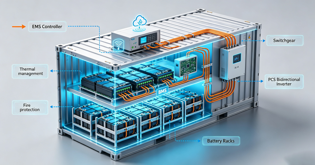
The shortest answer: a battery energy storage system is built from four component layers — the battery itself (cells, modules and racks that store the energy), the PCS (the power conversion system that moves energy between DC and AC), the BMS (the battery management system that protects and monitors the cells), and the EMS (the energy management system that decides when to charge and discharge) — plus a balance of system that cools, protects and connects them. The battery energy storage system components are always present in some form, at every scale from a wall unit to a grid container; what changes with scale is how much of each layer is visible, and who supplies it.
Ask a datasheet what a BESS contains and you will usually see a capacity figure and a power figure. Ask an engineer and you will get a wiring diagram with a dozen boxes. The truth for a buyer sits in between: four functional layers that every system shares, each with its own suppliers, specifications and failure modes. Understanding them is what turns a BESS purchase from a single-line item into a managed set of decisions — and it is the map for the component-level guides this site publishes on BMS selection, inverter choice and system architecture. For the broader question of what a BESS is and why it exists, start with #08 what is battery storage; for how storage technologies compare, see #11 types of energy storage systems.
Layer 1: The battery
The storage layer begins with cells, the electrochemical units where energy actually lives. Cells are assembled into modules — mechanically grouped, fused and sensed building blocks — and modules into racks or cabinets that carry the system voltage. The chemistry decision (LiFePO4 versus nickel-rich lithium, and legacy lead-acid) sets the safety profile, cycle life and energy density; the format decision (prismatic large-format cells dominate modern stationary storage) sets the mechanical and matching economics. What the buyer sees is the rack: its voltage platform, capacity, and the quality of the cell matching behind it — the layer where grading and binning decide whether the nameplate survives a decade of duty.
Layer 2: The PCS
The power conversion system is the bidirectional inverter at the heart of the electrical design. It converts DC battery energy to AC for the site or the grid, and AC back to DC when the battery charges. Its rating defines the system’s power — how fast energy can move — while the battery defines how much. The PCS also implements the grid-interface behaviour: synchronisation, reactive power, and the ride-through and disconnection rules the local grid code requires. At residential scale the PCS is the familiar hybrid inverter, sometimes integrated with the battery in one cabinet; at commercial scale it is a separate unit with its own enclosure, cooling and protection. The selection questions specific to this layer are covered in #17 how to choose a storage inverter, and where the PCS connects relative to the solar side — the AC-versus-DC coupling decision — is the subject of #43 AC vs DC coupling.
Layer 3: The BMS
The battery management system is the battery’s guardian and translator. It monitors cell voltages, currents and temperatures; it enforces the protection limits that keep every cell inside its safe window; it balances the string so no cell drifts toward the limits ahead of the rest; and it reports the battery’s state — charge, health, faults — to the layers above. The BMS is also where safety begins: most electrical abuse conditions that could escalate into thermal events are interrupted at this layer, which is why fire-safety analysis treats the BMS as the first of several protection layers rather than a convenience feature. A full treatment of the BMS — what it does, how it protects, how to select one — is in #28 BMS 101 and #49 BMS protection mechanisms.
Layer 4: The EMS
The energy management system is the least visible layer and the most often confused with the BMS. The division of labour is clean: the BMS protects the battery; the EMS operates the system. The EMS decides when to charge and discharge against a purpose — maximising solar self-consumption, arbitraging time-of-use tariffs, providing backup reserve, limiting peak demand — and it does so by setting power commands for the PCS within the limits the BMS reports. It is also where the user experience lives: dashboards, schedules, remote monitoring, and the interfaces to site systems, meters and tariff data. In small residential systems the EMS functions may be folded into the inverter’s control logic; in commercial systems the EMS is a distinct platform, often third-party, integrating the BESS into a wider energy strategy.
| Layer | What it does | Key spec for buyers | Typical failure mode |
|---|---|---|---|
| Battery | Stores energy (cells → modules → racks) | Capacity, chemistry, cell matching standard | Capacity fade; weak-cell imbalance |
| PCS | Converts DC ↔ AC; interfaces with the grid | Power rating, efficiency, grid-code compliance | Power-stage faults; grid-rule mismatch |
| BMS | Protects and monitors cells; balances the string | Sensing granularity, protection thresholds, protocol | Protection gaps; communication dropouts |
| EMS | Decides when to charge and discharge; user platform | Control modes, integrations, monitoring quality | Poor strategy fit; integration failures |
Reading a tender or a proposal with this four-layer map in hand changes what stands out. When a document lists battery energy storage system components as a single package line, the integration responsibility is undefined; when it names the layers and their interfaces, the risk has an owner. Procurement teams that specify battery energy storage system components layer by layer — with the interface tests between them written into acceptance — consistently report fewer commissioning surprises than teams that buy a nameplate and a warranty page.
How the layers talk to each other
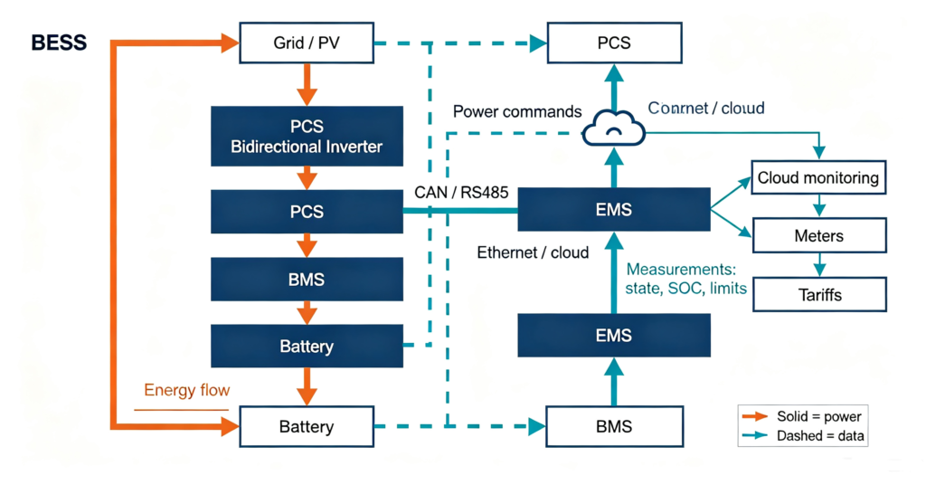
A BESS in operation is a conversation with a strict etiquette. The BMS reports — continuously — what the battery can safely do right now: its state of charge, its limits, its faults. The EMS decides what the system should do given that report, the site’s loads, the tariff and the weather. The PCS executes, moving the commanded power while staying inside everything the BMS declared. When any layer withdraws its consent — the BMS hitting a limit, the EMS changing strategy, the PCS seeing a grid event — the system degrades gracefully: derate, then disconnect, in that order. Buyers who internalise this chain can read any BESS product literature quickly: every serious specification answers who monitors, who decides, who converts, and on which protocol each conversation runs.
That protocol question is more than a detail, because the interfaces between layers are where integration failures live. The battery-to-PCS conversation typically runs over CAN or RS485 with vendor-specific protocols layered on top; the handshake rules and the compatibility-list governance around them are covered in #18 battery-inverter compatibility. A system whose layers were designed to talk to each other — or at least tested together — is a system; a collection of well-specified parts that have never met is a project risk wearing a single-line diagram.
The map also explains why component-level knowledge pays at contract time. Suppliers of battery energy storage system components quote different scopes behind similar words: one “BESS supply” covers racks and BMS only; another adds the PCS; a third includes integration and commissioning. Layer literacy is what lets a buyer compare those quotes line by line instead of discovering the gaps at installation.
The balance of system
Around the four layers sits everything that makes them survive in the real world. Thermal management — air or liquid cooling — keeps cells in their operating window, and the choice between them changes both first cost and lifetime performance. Fire protection spans detection, barriers, venting and suppression, and is governed by installation codes. Enclosures and switchgear provide the structure, isolation and protection ratings. Transformers and grid connection equipment appear at larger scales. None of these store or convert energy, but a BESS project that treats them as afterthoughts discovers their cost and schedule weight during permitting — which is why experienced buyers read the balance of system as carefully as the headline components. The cooling trade-off is covered in #36 liquid vs air cooling, and the fire-safety stack in #44 BESS fires and safety codes.
What buyers should ask about each layer
- Battery: which chemistry and format, what matching standard, and what documentation travels with each lot?
- PCS: what power rating and efficiency at the operating band, and which grid codes are certified for which firmware versions?
- BMS: what sensing granularity, which protection thresholds, and is the protocol supported by the chosen PCS?
- EMS: which control modes does the project actually need, what does the monitoring platform expose, and who configures the strategy?
- Integration: has this exact battery–PCS pairing been tested together, and who owns the compatibility answer when firmware updates land?
- Balance of system: what cooling, fire protection and enclosure ratings does the site’s code path require?
Q.What is the difference between a BMS and an EMS?
The BMS works at the battery level: it monitors and protects the cells, balances the string and reports the battery’s state and limits. The EMS works at the system level: it decides when to charge and discharge based on tariffs, loads and strategy, and sends power commands accordingly. The BMS can always veto what the EMS commands; the EMS cannot override what the BMS prohibits.
Q.Is the PCS the same as an inverter?
In a BESS, the PCS is a bidirectional inverter: it converts battery DC to AC when discharging and AC to DC when charging, which a standard solar inverter cannot do. At residential scale the PCS is usually called a hybrid inverter. At commercial and utility scale it is a dedicated unit with grid-interface functions of its own.
Q.Can the four components come from different suppliers?
Yes, and at commercial scale they often do — batteries, PCS and EMS are each specialist markets. The condition is integration: the interfaces, especially between battery and PCS, must be tested and supported pairings. Split sourcing broadens choice and concentrates the project risk into the integration responsibility, so establish who owns that answer before the order, not after the first fault.
Q.Which component fails most often?
Field statistics vary by fleet and reporting, but integrators consistently point at power electronics and interfaces — the PCS and the communication links between layers — as the most common sources of downtime, while the battery itself tends to fade rather than fail. This is one more reason the pairing and protocol questions deserve procurement weight.
Q.Does a home battery have all four layers?
Yes, but folded together. A residential wall unit contains cells and a BMS inside its enclosure, with the PCS often integrated or paired as a hybrid inverter, and the EMS functions running as the control logic and app platform. The layers are architectural, not physical boxes — which is exactly why understanding them helps even when the product is one cabinet.
Next step: go one layer deeper
Each component layer has its own selection guide on this site. Pick the layer you are responsible for.
- Start from the system view in #08 what is battery storage
- Master the BMS layer via #28 BMS 101
- Choose the PCS with #17 storage inverter selection
- Set the architecture with #43 AC vs DC coupling
- Ask leekooenergy how the battery, BMS and integration layers are specified across our BESS range