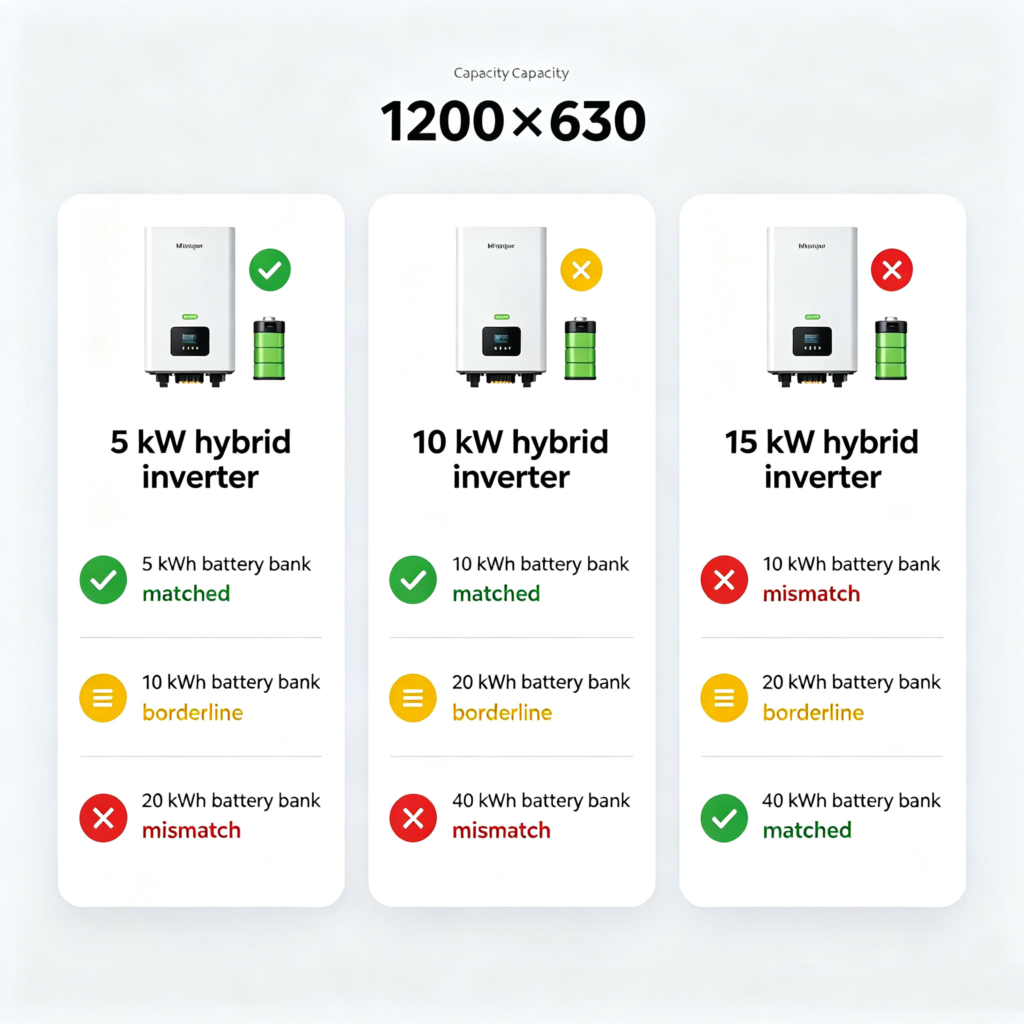
Hybrid inverter sizing and battery capacity have to match on three numbers: the inverter’s continuous AC power in kilowatts, the battery’s usable energy in kilowatt-hours, and the BMS continuous charge and discharge current in amps. Get any one wrong and the system underperforms — a 5 kWh battery with a 10 kW inverter will discharge in half an hour; a 40 kWh battery with a 5 kW inverter will refuse to charge at its rated rate. The inverter nameplate tells you how fast the system can move energy; the battery kWh tells you how much energy there is; the BMS continuous current is the bridge — and the rule is that all three must agree on the same working power and energy for the loads the buyer actually has.
Sizing is the most common place a residential or small commercial storage project goes wrong, because the inverter box and the battery box are sold separately and the matching is left to the installer. This article is written for the buyer or installer who has chosen the hybrid topology and now has to match an inverter kW to a battery kWh, and for the distributor who stocks both and has to publish a compatibility chart that does not lie. The hybrid inverter selection framework is in #17 how to choose a storage / hybrid inverter; the battery sizing by daily load is in #9 how to size a home battery; this article stays on the inverter-to-battery match.
The three numbers that must agree
A hybrid inverter and a battery bank talk through a single set of electrical numbers. The inverter has a continuous AC output rating in kilowatts and a maximum DC charge/discharge current. The battery has a nameplate capacity in kilowatt-hours, a usable capacity depending on depth of discharge, and a BMS continuous current in amps that translates into kilowatts through the battery voltage. The three numbers must agree on the same working power and energy, or the system will be limited by whichever number is smallest. The way the BMS protects the battery is in #49 BMS protection; for sizing, the three numbers come from three different spec sheets and have to be combined by the installer.
| Number | Where it comes from | Why it matters for sizing |
|---|---|---|
| Inverter continuous AC output (kW) | inverter datasheet | limits how much AC power the system can deliver to the loads; also limits AC charge power when refilling the battery from the grid |
| Battery nameplate capacity (kWh) | battery datasheet | total stored energy; multiplied by usable DoD (≈0.8 for LFP) gives usable energy |
| BMS continuous charge/discharge current (A) | battery BMS datasheet | limits how fast the battery can be charged or discharged; multiplied by battery voltage gives max battery kW |
| PV array peak power (kWp) | PV array datasheet | limits how fast PV can fill the battery; usually not the bottleneck at residential scale |
| Daily energy budget (kWh) | load audit or measured data | the energy the system has to deliver every day; drives battery kWh |
| Peak load (kW) | load audit or measured data | the highest simultaneous AC load; drives inverter kW |
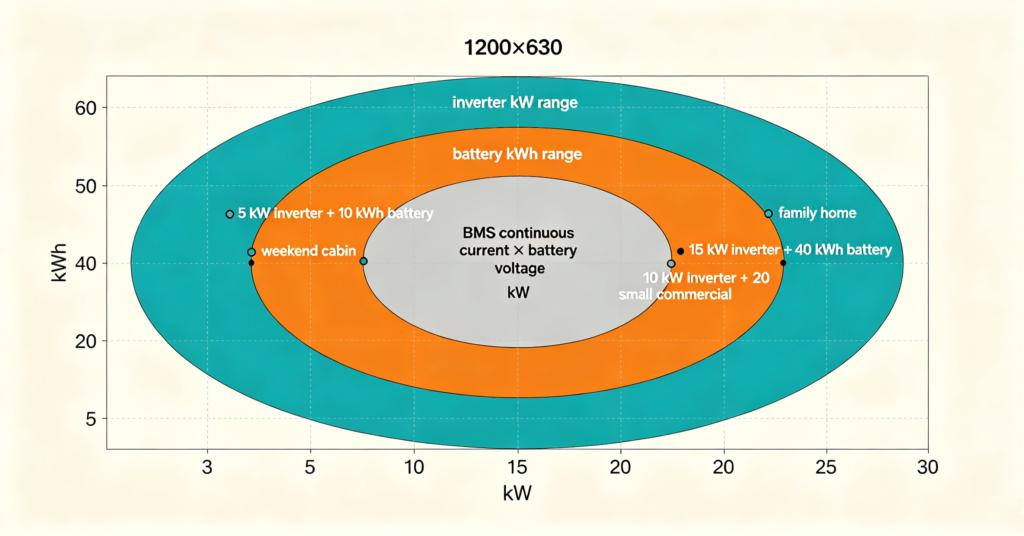
The rule is to size the inverter to cover the peak load with headroom for PV export, size the battery to cover the daily energy budget with one or two days of autonomy, and confirm the BMS continuous current can deliver the inverter’s continuous AC output through the battery voltage. The last check is the one most often missed, and where the sizing errors hide.
Over-sizing and under-sizing: how to read the symptoms
Two sizing mistakes show up in the field. Under-sizing the inverter for the battery produces a system that can hold energy but cannot deliver it; over-sizing the inverter for the battery produces a system that can deliver power but runs out of energy. The third mistake — under-sizing the BMS continuous current for the inverter — produces a system that the BMS throttles.
| Mistake | Symptom | Root cause | Fix |
|---|---|---|---|
| Inverter undersized for the battery | battery charges slowly even on a sunny day; inverter clips at full output well before peak load | inverter kW below battery max kW (voltage × BMS amps) | upsize the inverter or downsize the battery |
| Inverter oversized for the battery | inverter delivers full kW for a few minutes, then drops; battery SoC swings hard between 100% and 20% | inverter kW above battery kW × 1 C-rate | downsize the inverter or upsize the battery |
| BMS continuous current undersized for the inverter | BMS cuts off charge or discharge at high power; logs show “BMS overcurrent” or “BMS protection” | BMS amps × battery voltage < inverter continuous kW | replace the battery with one whose BMS rating matches, or limit inverter kW |
| Battery undersized for the daily load | system runs out of energy overnight every day; daily cycling at >80% DoD | battery kWh × DoD < daily load kWh | add battery modules; the inverter usually does not need to change |
The BMS cut-off is the symptom that sends installers back to the spec sheet most often, because neither the inverter nor the battery logs a useful error — the system just stops. The way to design around the limit is in #61 battery energy storage system design.
A worked example across residential scale
Three worked examples show how the rule applies at common residential scales. The numbers use the same daily budget method in #9 how to size a home battery; the example is a hybrid inverter paired with an LFP battery at the depth of discharge the chemistry allows.
| Profile | Daily load | Peak load | Recommended battery (LFP) | Recommended hybrid inverter | Matched? |
|---|---|---|---|---|---|
| Weekend cabin, hookup most nights | ≈5–10 kWh | ≈3 kW | ≈10 kWh | ≈3–5 kW single-phase | yes |
| Family home, partial solar | ≈15–25 kWh | ≈7 kW | ≈20 kWh | ≈8–10 kW single-phase or split-phase | yes |
| Small commercial with three-phase service | ≈40–80 kWh | ≈15 kW | ≈40–60 kWh | ≈15 kW three-phase | borderline (verify BMS amps) |
The “borderline” label on the small commercial row is the rule’s most useful output — it tells the buyer to verify the BMS continuous current before signing the purchase order. For a 40 kWh battery paired with a 15 kW inverter, the BMS has to deliver roughly 300 A at 48 V (or 150 A at 96 V), and not every BMS does that without active cooling or a larger cell format. The 280Ah vs 314Ah cell choice that affects the BMS design is covered in #25 LFP cells 280Ah vs 314Ah.
Reading the spec sheets: the cheat sheet
The three numbers the spec sheets have to publish, and the questions the buyer should ask if any of them is missing:
- Inverter: continuous AC output (kW), peak surge (kW for seconds), max DC charge current (A), max DC discharge current (A), supported battery voltages (V).
- Battery: nameplate capacity (kWh), usable capacity at the recommended DoD (kWh), BMS continuous charge current (A), BMS continuous discharge current (A), BMS peak current and duration (A × seconds).
- Both: the supported BMS protocol list on the inverter, and the supported inverter list on the battery, both with the firmware version pinned to the date of the certificate.
If any of these numbers is missing or marked “TBD”, the spec sheet is incomplete and the sizing rule cannot be applied. The supplier-evaluation logic is in #21 how to evaluate battery manufacturers.
Buying for a fleet or a distributor catalogue
For a fleet buyer or distributor, the sizing rule translates into a stock-keeping rule: standardise on a small number of matched inverter-battery pairs and publish the sizing envelope for each. Three rules keep the catalogue honest:
- Publish matched sets, not loose items: every battery has a recommended inverter kW range and a maximum; every inverter has a recommended battery kWh range and a maximum continuous discharge current.
- Publish the BMS amps: the BMS continuous charge and discharge current in amps is the number the installer’s sizing calculator needs.
- Publish the firmware pinning: inverter and BMS firmware versions must be locked to the protocol list, with a refresh date, so an installer can confirm the system still works after a firmware update.
Q. How many kW hybrid inverter for a 10 kWh battery?
A 10 kWh LFP battery paired with a 5 kW hybrid inverter is the most common residential match: the inverter can charge the battery at its rated continuous current, and the battery can deliver the inverter’s full output for about 90 minutes at the rated DoD. A 3 kW inverter is fine if the peak load is low; a 10 kW inverter is over-sized and the battery will discharge in 30 minutes.
Q. What happens if the hybrid inverter is too big for the battery?
The inverter delivers its full kW for as long as the battery can supply it, then either the BMS cuts off (if the BMS continuous current limit is exceeded) or the battery voltage sags. The result is short runtime, frequent BMS alarms, and an inverter that is rarely at full load — wasted capital.
Q. What happens if the hybrid inverter is too small for the battery?
The battery charges and discharges slowly because the inverter kW is the bottleneck. A 40 kWh battery paired with a 5 kW inverter will take 8 hours to charge from empty, which is longer than any single sunny day in winter. The system still works but never reaches full state of charge.
Q. Does the BMS continuous current limit really matter?
Yes. The BMS is the safety device that disconnects the battery if its own ratings are exceeded. If the inverter asks for more current than the BMS allows, the BMS opens the contactor and the system stops with a “BMS protection” log. The fix is to size the inverter to stay within the BMS amps, not to bypass the BMS.
Q. Can I add more battery modules to a hybrid inverter system later?
Usually yes, as long as the inverter kW is large enough for the new battery’s continuous kW and the BMS protocol list still matches. The rules are the same as for the original sizing: confirm the inverter kW, the battery kWh and the BMS continuous current all agree.
Next step: write the three numbers on the same line
The right hybrid inverter and battery match is the one where the inverter continuous kW, the battery usable kWh and the BMS continuous current all line up on the same working envelope — and where the daily load and the peak load both fit inside that envelope.
- Start with the inverter selection framework in #17 how to choose a storage / hybrid inverter
- Size the battery by daily load in #9 how to size a home battery
- Confirm the BMS continuous current in #32 how to choose a LiFePO4 BMS
- Verify the protocol match in #18 battery-inverter compatibility
- Ask leekooenergy for the inverter-battery match table that lists the inverter kW, the battery kWh and the BMS continuous current on the same line — and the firmware version that locks them — a hybrid inverter system whose three numbers agree by construction