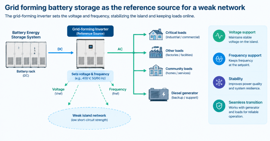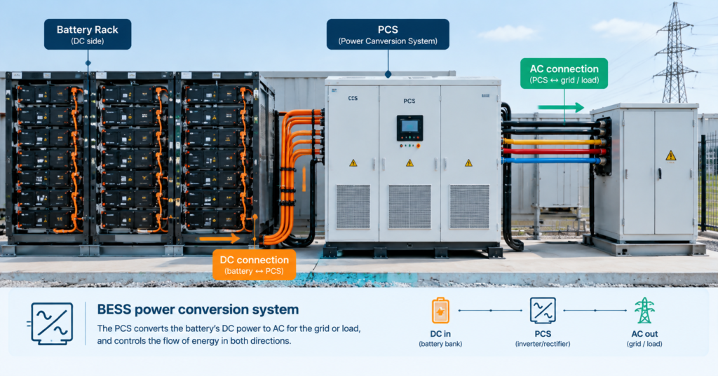
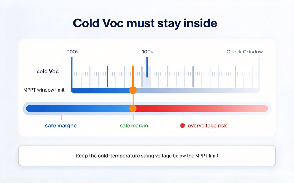
A solar inverter connection diagram is the schematic that shows the order in which the array, the protection devices, the inverter, the battery and the loads connect — and the isolation and earthing that must sit between them. This guide walks through that order stage by stage, explains what each isolator and protective device is for, and sets out the checks that separate a compliant installation from one that merely works on the day.
Most inverter problems that present as “the inverter is faulty” are wiring problems: an isolator in the wrong place, an undersized cable, a missing earth bond, or a battery connected to a unit that was never configured for it. Reading a solar inverter connection diagram before the hardware arrives prevents nearly all of them, and it makes the commissioning conversation with your electrician far shorter.
The order, stage by stage
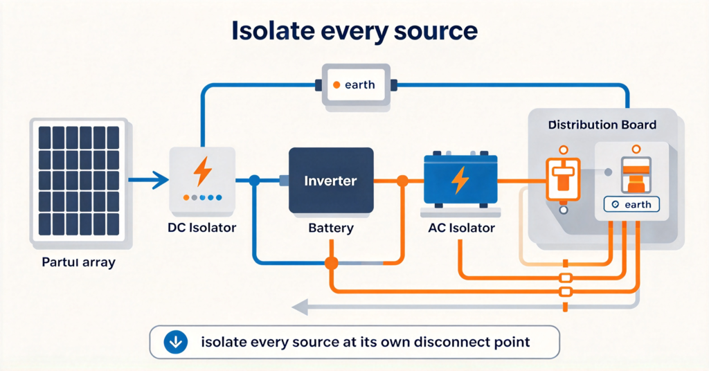
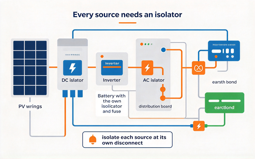
Working from the array toward the loads, the sequence is: PV strings to a DC isolator, then to the inverter’s DC input (passing through a charge controller or the inverter’s own MPPT stage if there is one); the battery to a DC isolator and an overcurrent device, then to the inverter’s battery terminals; the inverter’s AC output to an AC isolator, then to the distribution board and the loads; and the whole system bonded to a common earth.
The reason the order matters is isolation. Every source needs a means of being disconnected so the equipment downstream can be worked on safely, and a PV array is a source that cannot be switched off at the panel — it is live whenever there is light. That is why the DC isolator sits immediately at the array side rather than somewhere convenient indoors.
Isolators and protective devices
A DC isolator on the array side lets the PV input be disconnected for service. A second DC isolator and an overcurrent device on the battery side does the same for the battery, and the overcurrent device is not optional — a battery can deliver very large current into a short, and the cable must be protected against it. Fuse or breaker rating follows the cable size and the battery’s capability, not the inverter’s rating.
On the AC side, an AC isolator between the inverter and the distribution board lets the inverter be isolated from both the loads and, critically, from the grid or any backup generator. Where the system can feed energy back into a grid connection, the interconnection arrangement is a utility matter as much as an electrical one and must follow the local rules rather than a generic diagram.
| Position | Device | Purpose |
|---|---|---|
| Array side | DC isolator | Disconnect a source that cannot be switched off |
| Battery side | DC isolator plus fuse | Isolate and protect against short-circuit current |
| AC output | AC isolator | Isolate from loads and grid |
| Whole system | Earth bond | Give fault current a safe path |
Earthing and bonding
Every exposed conductive part — the inverter chassis, the battery enclosure, the mounting frames — should be bonded to a common earth so that a fault has a low-impedance path and the protective device actually operates. An unbonded chassis can sit at a dangerous potential indefinitely without tripping anything, which is the failure mode earthing exists to prevent.
Follow the inverter manufacturer’s earthing instructions rather than a generic diagram, because the DC side of some topologies is referenced differently and an incorrect bond can create a fault loop. Where a generator or a changeover switch is involved, the switching arrangement determines where the neutral-earth bond sits, and getting that wrong is a common and serious error. The solar wiring diagram covers the house-level view of the same subject.
Cable sizing and voltage drop
DC cable between the battery and the inverter carries high current at low voltage, which makes it the most common place for a voltage-drop problem. Undersized cable wastes energy as heat, and on the battery side it also causes the inverter to see a voltage that sags under load — which can trigger a low-voltage cutoff on a battery that is actually well charged.
Size the cable for the current and the run length, and keep the run short. The practical guidance is to place the inverter close to the battery bank and to increase the cross-section as the run grows. Torque every termination to specification, because a high-current DC connection that is slightly loose will heat, oxidise, and eventually fail.
Configuration before energising
A solar inverter connection diagram shows the physical topology, but the unit also has to be told what is connected to it. Battery chemistry, nominal voltage, charge limits and, on hybrid units, the grid and generator behaviour all have to be configured before the system is energised. A correctly wired system with the wrong battery chemistry selected will charge incorrectly and can damage the bank.
Confirm the configuration against the battery’s data sheet, not against a default. Then energise in stages: array isolated, battery connected and verified, then the AC side, then the array. That sequence localises any fault to the stage that was just connected. The inverter not charging troubleshooting guide covers the symptoms when this goes wrong, and the all in one solar inverter guide guide covers units where several of these stages share one enclosure.
Where the hardware lives
Inverter siting affects the wiring as much as the topology. Mount it close to the battery, in a ventilated space, out of direct sun, and where the display and the isolators can actually be reached. An inverter installed where nobody can read it or isolate it will be poorly maintained regardless of how good the diagram was.
Outdoors, use an enclosure rated for the site and ventilated for the inverter’s waste heat, with cable entries glanded and drained. The outdoor inverter enclosure guide guide covers that in detail, and the AC versus DC coupled storage comparison explains how the topology changes depending on where the battery sits in the system.
Commissioning checks
Before handover, verify polarity at every DC termination, confirm the earth bond continuity, check that every isolator actually isolates what it is supposed to, and record the torque values. Confirm the inverter reports the correct battery voltage and that it charges and discharges as configured under a real load.
Label everything. A labelled isolator and a labelled cable saves the next person — who may be you in three years — from tracing circuits by hand. For chisidal-supplied systems, send the proposed topology and the cable runs, then ask for the wiring schedule and the commissioning checklist that match them.
Reading the diagram as a checklist
Work from the diagram inward: isolators at every source, a fuse sized for the cable, a common earth bond, short thick DC runs, and the configuration set before anything is energised. Most inverter faults are wiring faults wearing a different label.
Q. solar inverter connection diagram?
A solar inverter connection diagram is the schematic showing the order in which the array, protection devices, inverter, battery and loads connect, plus the isolation and earthing between them. It is the reference for a safe, serviceable installation rather than just a wiring sketch.
Q. What order should I wire a solar inverter?
From the array inward: PV strings to a DC isolator to the inverter DC input; battery through its own isolator and fuse to the battery terminals; AC output through an AC isolator to the distribution board; and everything bonded to a common earth.
Q. Why does the array need its own isolator?
A PV array cannot be switched off at the source — it is live whenever there is light. The DC isolator gives a means of disconnection so downstream equipment can be worked on safely.
Q. Do I need a fuse between the battery and the inverter?
Yes. A battery can deliver very large current into a short, and the cable must be protected against it. Size the device for the cable and the battery’s capability, not for the inverter’s rating.
Q. How do I size the battery-to-inverter cable?
For the current and the run length. Undersized cable wastes energy as heat and can cause a voltage sag that trips a low-voltage cutoff on a battery that is actually charged. Keep the run short and increase cross-section as it grows.
Q. Where should the inverter be earthed?
Bond the chassis and every exposed conductive part to a common earth so fault current has a low-impedance path. Follow the manufacturer’s instructions, because DC-side referencing differs between topologies.
Q. What should I configure before switching on?
Battery chemistry, nominal voltage and charge limits, plus grid and generator behaviour on hybrid units. Confirm against the battery data sheet rather than accepting defaults, and energise in stages.
Next step: send the topology before the hardware
Most inverter faults are wiring faults. Send the proposed layout and cable runs for a wiring schedule and commissioning checklist.
- Check the house-level view in solar wiring diagram
- If the inverter goes outdoors, read outdoor inverter enclosure guide first
- For chisidal, send your usage and site details, and we will come back with product prices, lead time and warranty information.