Solar panel drawing is the set of diagrams that define how a PV system is laid out, wired and structurally supported. The three drawings every installer reads are the single-line diagram for electrical topology, the array layout for module and racking placement, and the structural load drawing for roof or ground mounting. This guide explains what each drawing shows, the symbols to recognize, and how to read and check a set before any panel goes up.
Most procurement and installation errors trace back to a drawing that was skimmed rather than read. A drawing is a contract between the designer, the inspector and the crew, so knowing which line carries what load is not optional.
What a solar panel drawing set contains
A complete solar panel drawing set is rarely a single sheet. It is a package of coordinated documents, and the three that decide whether a job is buildable are the single-line diagram, the array layout, and the structural load calculation. Each answers a different question: how power is routed, where each module sits, and whether the roof or frame holds it.
The electrical and structural drawings must agree, because the layout sets the weight and wind exposure the load drawing must survive. When they disagree, assume none was checked and stop until reconciled. Reading them as one set is the first habit a competent crew builds.
This is where the bill of materials is born. The module count, racking type and inverter choice shown in the drawings drive the pv panel kits a buyer receives, so a drawing review is also a procurement review. The solar module components guide explains the parts those drawings reference, but the drawing is what places them.
Single-line diagram: symbols and what to read
The single-line diagram, often called an SLD, is the electrical map drawn as if every paired conductor were one line. It shows the source, inverter, disconnects, service-panel connection and any storage using standardized symbols rather than a literal wire view. Its job is to make the power path and protection devices legible at a glance.
The symbols to recognize are few but non-negotiable. A circle or box marks the inverter, a battery symbol marks storage, a switch marks a disconnect, and a grounded triangle marks the service-panel connection. The values next to them matter more than the shapes: string voltage and current, inverter rating, conductor size and every overcurrent rating.
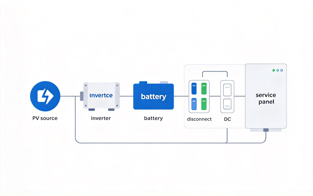
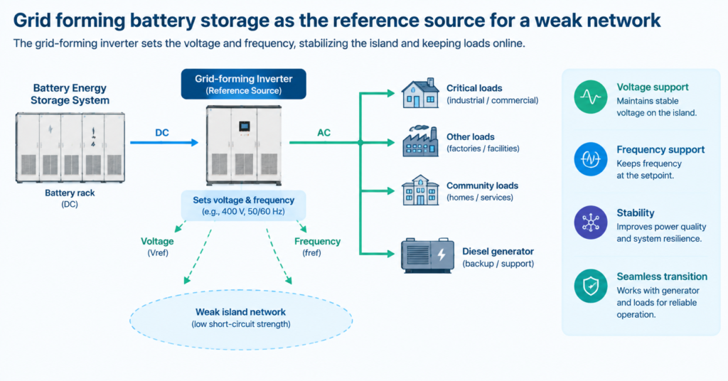
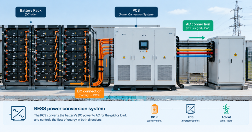
Coupling matters here. An AC-coupled battery routes storage through a second inverter on the AC side, while a DC-coupled design places the battery on the same DC bus as the array, and the diagram tells you which you are building. The choice is covered in the ac vs dc coupled solar pv battery storage discussion, but the single-line diagram is where you confirm it. When the array pairs with storage, the DC-side values also set the solar panels with battery storage hardware you source, so read those lines twice.
Array layout drawing: spacing, orientation and placement
The array layout drawing is the physical plan. It shows where each module row sits, the spacing between rows, the azimuth and tilt, and how strings group before the inverter. Its purpose is to turn a roof or field into a coordinate map the crew can lay out with a chalk line.
Row spacing is not aesthetic. It sets inter-row shading, which changes annual yield, and the layout should state the spacing assumption, the local latitude and the worst-case winter sun angle. The how many solar panels do i need question feeds the module count, but the layout is what proves those modules fit the area without shading each other.
Placement also drives the structural drawing. Every module on the layout adds a point load and a wind-catch area, so the layout and load plan are two views of the same weight. The racking that holds the array, detailed in the solar panel racking system guide, must match the attachment points the layout assumes, or the structural calculation is void.
Structural load drawing: weights, wind and snow
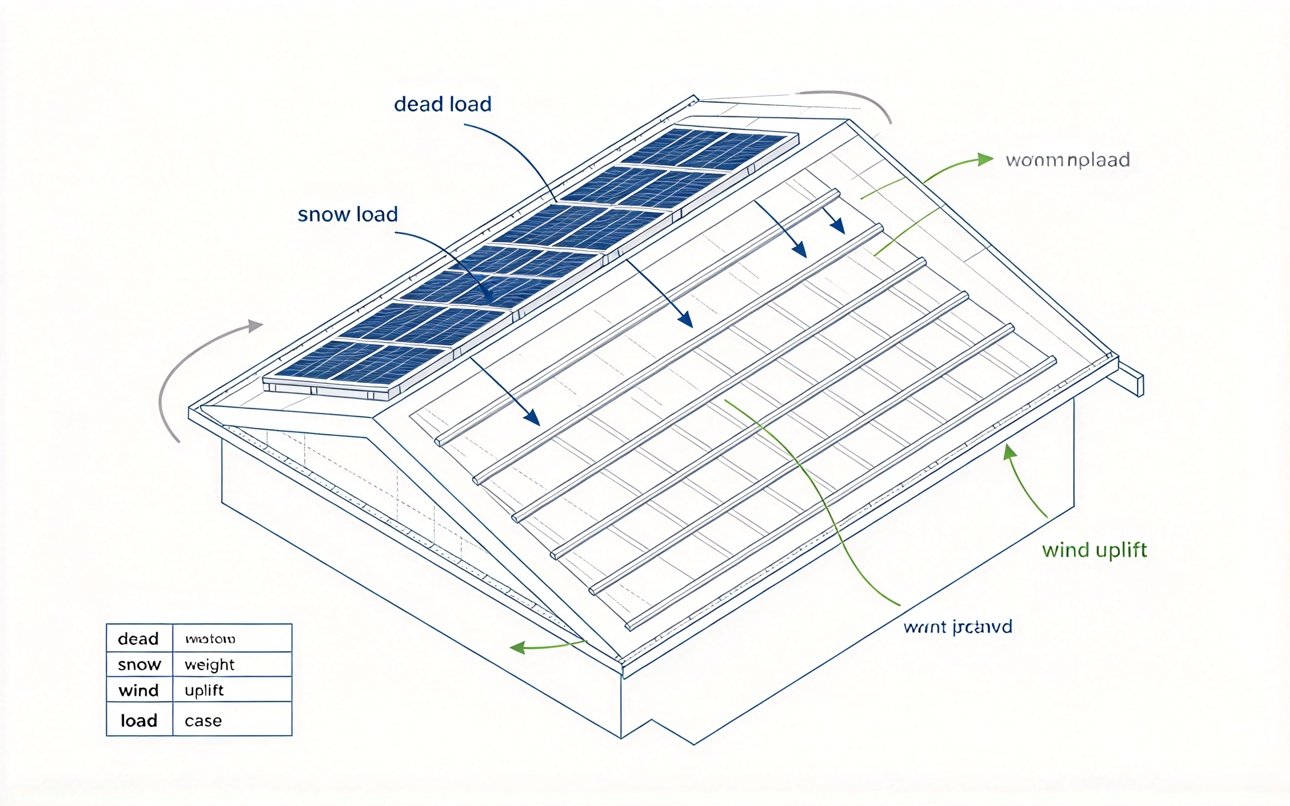
The structural load drawing, or the calculation it summarizes, proves the mounting surface can carry the array. It lists the dead load from modules and racking, the snow load where applicable, and the wind and uplift loads that try to peel the array off the roof. For ground mounts it covers the post and footing design.
This drawing is where jurisdiction and building code meet the array. A flat commercial roof and a sloped residential roof are not the same problem, and the load plan must name the applicable code edition and the roof type it was calculated for. If the drawing shows generic numbers with no reference to the actual building, it is a hope, not a calculation.
Standards and who signs the drawing
The drawings are governed by wiring and building standards, and the names that matter are the electrical code, the building code, and equipment safety standards from bodies such as IEC, IEEE and UL. Which edition applies depends on the country and local amendment, so the drawing should name the editions it was designed to and the engineer of record should sign it.
A signature is the difference between a drawing and a sketch. The professional who stamps the set takes responsibility for the numbers, and that stamp is what the permitting authority and inspector accept. The solar panel installation permits guide covers the permit step, but the stamped drawing is what the permit is built on. Treat any set without a responsible signature as incomplete.
How to read a solar panel drawing set, step by step
Reading a set in a fixed order prevents the most common mistakes, because it forces the electrical and structural views to be checked against each other before anyone climbs a ladder. Follow this sequence:
- Start with the title block: project name, revision, signature and cited code editions. A drawing without these is unfinished.
- Read the single-line diagram and list every voltage, current and breaker rating, then confirm each matches the named equipment.
- Open the array layout and total the module count, spacing and azimuth, checking the yield assumption is stated.
- Open the structural load drawing and confirm the dead, snow and wind loads are for this exact building, not a generic one.
- Cross-check that the racking attachment points in the layout match the connection points the load drawing relies on.
- Flag every mismatch to the designer before procurement; a corrected drawing beats a returned shipment.
Common drawing mistakes to catch before install
The same errors recur across projects, and most are visible on the paper if you know to look. The table below lists each failure, why it matters and the check that catches it.
| Drawing error | Why it matters | Check that catches it |
|---|---|---|
| SLD values do not match equipment | Wrong breaker or conductor trips or overheats | Compare every rating on the SLD to the datasheet |
| Layout spacing omits winter shading | Annual yield drops after the first season | Confirm spacing, latitude and sun-angle assumption |
| Load plan uses generic numbers | Roof or footing may be under-designed | Require building-specific calculation and stamp |
| Racking points disagree across sheets | Structural assumption becomes void | Match layout attachment to load connection |
| No signature or code edition | Permit and inspection will reject it | Confirm stamp and cited code editions |
For chisidal packages that include storage, the single-line diagram must show the battery coupling clearly, because a mismarked coupling changes which inverter and DC hardware ship. A drawing review is the cheapest point to catch that error.
Q. What is a solar panel drawing?
A solar panel drawing is the set of diagrams that defines how a PV system is laid out, wired and structurally supported. It typically includes a single-line diagram, an array layout and a structural load drawing. The set is the contract between designer, inspector and crew.
Q. What does a single-line diagram show?
A single-line diagram shows the electrical path as if every conductor pair were one line: the PV source, inverter, disconnects, storage, service-panel link and each protection rating. The symbols identify the equipment, but the values beside them, such as string voltage and current, are what you verify.
Q. What is the array layout drawing for?
The array layout drawing is the physical plan that places each module row, sets inter-row spacing, states azimuth and tilt, and groups strings before the inverter. Its spacing assumption drives shading and yield, and sets the weight and wind area the structural drawing must survive.
Q. What does the structural load drawing prove?
The structural load drawing proves the mounting surface can carry the array by listing dead, snow and uplift loads from modules, racking and wind. It must be calculated for the specific building and stamped by a responsible engineer, or the permit and inspection reject it.
Q. Which standards apply to solar drawings?
Solar drawings are governed by the electrical code, the building code, and equipment safety standards from bodies such as IEC, IEEE and UL. The exact editions depend on the country and local amendments, so the drawing should name them. Confirm the cited editions against the target market before relying on them.
Q. How do I check a solar drawing set before install?
Read it in order: title block and signature first, then single-line values against datasheets, then layout count and spacing, then the building-specific load calculation, then cross-check racking points across sheets. Flag any mismatch to the designer before procurement; correcting paper beats returning hardware.
Next step: review the drawing before you order the hardware
A drawing set is cheaper to correct than a shipment is to return. Confirm the single-line values, the layout spacing and the stamped load plan agree, then order the matched kit.
- Match the module count and racking to the pv panel kits the layout implies so procurement and drawing stay in sync
- For chisidal, send your usage and site details, and we will come back with product prices, lead time and warranty information.